

A single pole double throw relay uses one common contact to select between two contact paths. In an ordinary monostable electromechanical version, the released coil leaves common connected to normally closed; energizing the coil transfers common to normally open. The coil controls the movement, while the contact terminals belong to the circuit being switched.
That description establishes the contact function. It does not identify the physical pins, the required coil supply or the load the contacts can switch. Those details come from the exact part’s drawing and ratings, including the full model suffix.
By ZiroSip
Single pole double throw relay states: COM, NC and NO
COM means common, NC means normally closed and NO means normally open. For the monostable relay discussed here, “normally” refers to its released, unactuated condition. It does not mean that the connected machine is operating normally or that a particular output is preferred.
| Ordinary monostable state | COM to NC | COM to NO |
|---|---|---|
| Coil released | Closed contact path | Open contact path |
| Coil actuated | Open contact path | Closed contact path |
This is a stable-state table, not a timing specification. It tells a reader which path belongs to each endpoint. It does not describe the transfer interval or establish behavior during a fault. Read any transition requirements from the manufacturer’s information for the selected device.
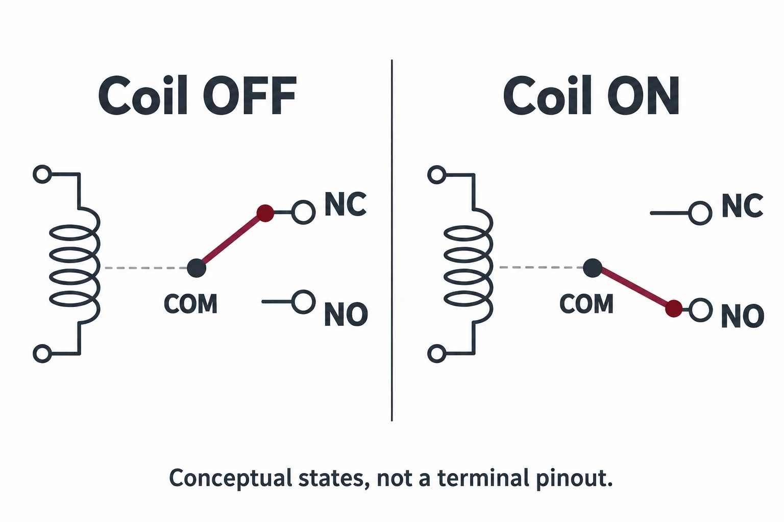
A useful way to read the figure is to follow one question at a time. First identify the coil’s stated condition. Then follow the movable contact from COM to the selected throw. Do not treat the coil symbol as a supply connection to COM or infer a terminal number from where a symbol sits on the page.
Keep the coil specification separate from the contact rating
The coil is the control input; the changeover contacts are the switching function. A relay specification therefore needs both sets of information. A coil voltage does not by itself tell you the contact voltage, current or load conditions.
The linked G5LE datasheet makes this distinction concrete: its ordering information identifies rated coil voltage, while its contact table gives load ratings separately. It also distinguishes SPDT and SPST-NO models within the same family. A familiar housing or family name is not enough to identify the required variant.
Choosing a 12V single pole double throw relay
When “12V” identifies the coil, it describes the control-side variant. Check whether the exact designation is DC or AC rather than assuming those are equivalent. The cited G5LE-1 ordering table includes a 12 VDC coil option; that is a manufacturer example, not a recommendation for an unspecified load.
A purchase request reading only “12V relay” leaves several questions unanswered: which contact form, which operating form, which mounting arrangement and which contact-duty rating? Put those requirements on separate lines so a supplier cannot satisfy one while changing another.
The same separation makes comparison easier. If the control-side data match but the contact-duty row is missing, the candidate is still unresolved. If the contact description matches but the coil variant differs, the candidate is also unresolved. Neither comparison is completed by a single prominent number on a product page.
Read a single pole double throw relay diagram in the stated view
A functional diagram explains connections; a terminal arrangement identifies where those functions appear on a particular part. A search for a single pole double throw relay wiring diagram can return either, so identify which drawing you are looking at before using its labels.
The G5LE sheet labels its terminal arrangement and internal connections as a bottom view. That viewing direction belongs to that drawing. It cannot be silently applied to a different relay or to a photograph taken from above. Record the view along with the part number before comparing physical positions.
- Identify the drawing: Functional symbol, internal connections, mounting pattern or terminal arrangement.
- Read its view label: Keep the drawing orientation with the record rather than relying on a familiar shape.
- Separate functions: Locate the coil group and the COM, NC and NO functions in the exact documentation.
- Check the full variant: Compare the contact form, operating form and coil information before accepting an alternative.
Two details that a generic diagram cannot settle
A latching relay can retain its selected state after its drive signal is removed. It therefore needs its own set/reset description; the coil-off row in the monostable table cannot identify its stored state. SPDT describes contact topology and does not, by itself, settle that operating behavior.
Coil polarity is another separate question. OMRON’s classification guide notes that some otherwise non-polarized relays with indicators or surge-absorbing diodes have polarity-sensitive coils. Use the exact product information rather than assuming every DC coil is reversible. No universal polarity or suppression-circuit connection follows from the SPDT label.
Compare candidates with a complete reading record
The following record is a proposed documentation tool. It helps a buyer or technician identify unanswered questions without pretending to validate an application from a generic diagram.
| Record item | Question to resolve |
|---|---|
| Exact identity | What is the full model, suffix and applicable drawing revision? |
| Contact form | Does the document specify the required common and two throws? |
| Operating form | Is this the required monostable or latching behavior? |
| Control input | What coil designation, supply type and polarity information are stated? |
| Contact duty | Which manufacturer rating applies to the intended load conditions? |
| Physical arrangement | Which viewing direction, mounting style and terminal arrangement are documented? |
Consider a hypothetical substitution where the original request calls for SPDT but a quotation offers a similarly named SPST-NO variant. The issue is not appearance: the offered contact form lacks the required changeover task. The discrepancy should be resolved before price or packaging is compared.
In a second hypothetical comparison, both candidates have a matching coil-voltage description and SPDT contacts, but one is monostable and the other latching. Their response after the drive signal disappears is different. A procurement note that records only voltage and contact count would miss that requirement.
These examples are reading exercises, not tested substitutions. A completed record should point to the exact documents that resolve each requirement. An unexplained blank remains a supplier question; it should not be filled by an internet pin diagram for another part.
For the related manually operated topology, the SPDT switch guide explains the pole-and-throw distinction. A relay adds a separate control input, so keep its coil and operating-form questions in the record even when the contact topology looks familiar.
References
- OMRON: Relay Classification and Operation — Relay operation, latching distinction and coil-polarity exceptions.
- OMRON: G5LE PCB Power Relay Datasheet — Separate coil/contact data, variant identification and bottom-view drawings; used as a manufacturer example.