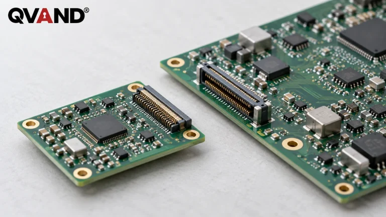


A circuit card assembly (CCA) is a printed circuit board populated with electronic components. The term identifies the assembled board. To know what a supplier will deliver, you also need an agreed specification for inspection, electrical testing, firmware, optional treatments and the accompanying records.
That distinction prevents an expensive misunderstanding: a board can look complete while the order still leaves its verification or integration requirements undefined. A useful purchase description connects the physical assembly to its released design and states the evidence needed to accept it.
CCA, PCB and PCBA describe different levels of the same build
The main distinction is between the bare board and the populated assembly. PCB commonly means the unpopulated printed circuit board. CCA, PCBA and PCA are often used for the board after components have been assembled onto it. Terminology varies between organizations, so the drawing and purchase specification remain the practical reference.
| Term | Usual meaning | What still needs defining |
|---|---|---|
| PCB / bare circuit card | The fabricated board before component assembly | Fabrication data, revision and board requirements |
| CCA / PCBA / PCA | A component-populated board | Build variant, inspection, testing and release records |
| Box build / system assembly | A larger assembly that may include boards, wiring and an enclosure | Integration tasks, configuration and system-level acceptance |
AdvancedPCB describes CCA and PCBA as overlapping terms and recommends comparing the actual scope. The name alone does not distinguish a simple card from a demanding program. It also does not establish an acceptance class, certification or complete functional-test coverage.
For purchasing, use the assembly part number and revision as the starting point. Then identify any build variant. A bare-board revision and a populated assembly revision need not represent the same decision: component selection, fitted options and released configuration belong in the assembly definition.
What is physically included in a circuit card assembly?
A CCA combines the board, fitted components and their interconnections. The board provides the mounting structure and conductive features. Components may include resistors, capacitors, integrated circuits and connectors. The assembly drawing and bill of materials determine which parts belong on that particular version.
Surface-mount assembly commonly involves solder-paste application, component placement and reflow soldering. Through-hole components can require additional soldering operations. The route depends on the design; a mixed assembly need not follow one universal sequence. Cleaning, protective coating and other operations should be specified where required, rather than assumed from the word “assembly.”
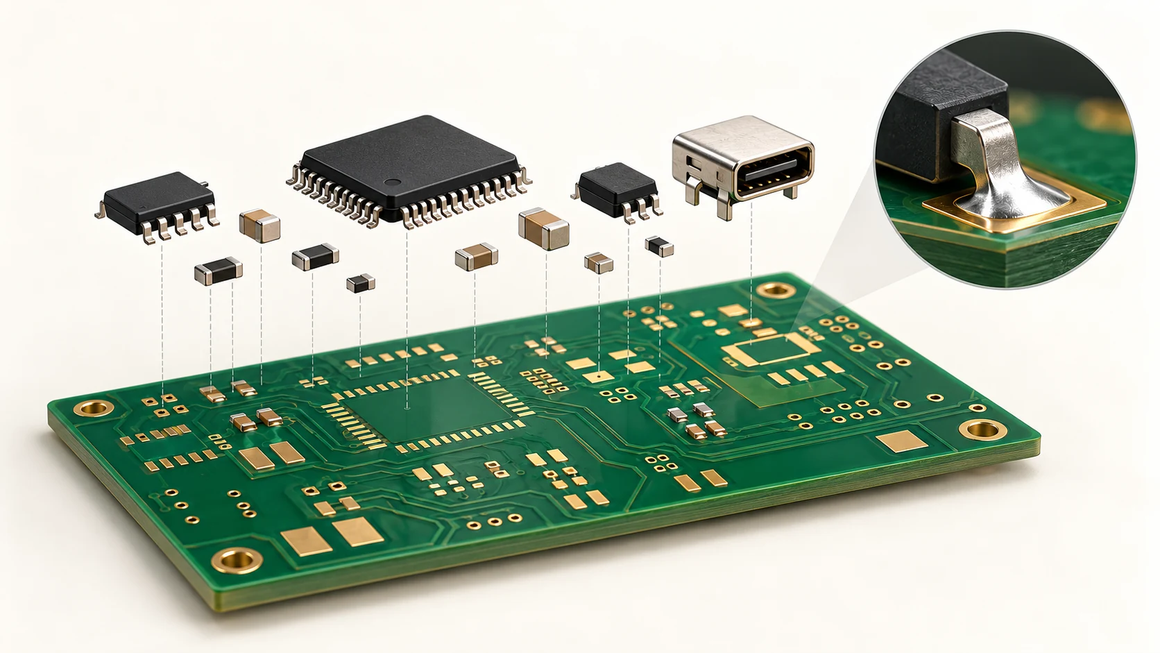
Keep the boundary between the board and the final product visible. Installing a CCA into a housing, attaching a cable harness and verifying the complete system may belong to a separate order. A populated board delivered to another factory is a different deliverable from a fully integrated unit.
The supplier needs a released build package, not just a board file
A fabrication file does not fully define component assembly. The supplier also needs an unambiguous parts list, assembly instructions and the agreed requirements for configuration and verification. Before release, confirm that the files describe the same build.
The bill of materials, or BOM, identifies the parts to fit. A component placement list, often called a CPL or centroid file, describes placement information such as coordinates, rotation and board side. JLCPCB’s file-preparation guide shows how reference designators link the placement data to the component list. Its required column format is supplier-specific, so use the assembler’s accepted template.
A practical release package should make these responsibilities explicit:
- Design owner: Identifies the released assembly, drawings, fitted options and documents that define it.
- Purchasing and component sourcing: Clarifies supplied parts, approved substitutions and who can authorize a change.
- Assembler: Confirms the received file versions, resolves conflicts and identifies any proposed deviation before building.
- Test owner: Defines the test instruction, configuration and acceptance record when testing is part of the order.
For example, a BOM may identify a component that is absent from the fitted variant. The release package should explain that difference rather than leave the operator to choose between conflicting files. A written clarification tied to the assembly revision is more useful than an informal instruction detached from the job.
Define the delivery in separate, checkable lines
Separate the physical build, verification and documentation in the purchase scope. This makes two quotations comparable and gives receiving staff a clear basis for deciding whether the delivered assemblies match the order.
The following matrix is a suggested purchasing aid, not an industry-mandated document set. Select the rows that matter for the assembly, then replace broad words such as “tested” or “complete” with the actual agreed requirement.
| Delivery line | Agree before the build | Ask for at receipt |
|---|---|---|
| Physical assembly | Assembly part number, revision and fitted variant | Identification matching the released build |
| Substitutions and deviations | Which changes need approval and who approves them | A record of approved changes, if any |
| Inspection | Applicable method, criteria and extent of inspection | The agreed inspection record and disposition of exceptions |
| Electrical or functional test | Named procedure, configuration and pass criteria | Results tied to the relevant unit or batch, as specified |
| Firmware, if required | Released image, revision and programming responsibility | The agreed programming or configuration record |
| Optional treatments | Required cleaning, coating or other defined operation | Evidence required by that operation’s specification |
| Packaging and identification | Protection needs and label contents for the delivery route | Correct packaging, quantities and traceable identification |
This approach also exposes exclusions. A quote that includes assembly and optical inspection may leave functional-test development to the customer. Another may include programming but rely on a customer-supplied image and fixture. Those arrangements can be reasonable; the problem is discovering the boundary only after the boards arrive.
Inspection and functional testing answer different questions
An inspection record should identify what was examined; a functional-test record should identify what operation was exercised. Neither should be used as a general promise that every possible failure has been ruled out.
Optical inspection, X-ray and electrical test can address different features. Their useful coverage depends on the board and the chosen method. Rather than asking whether an assembly is simply “quality checked,” ask which procedure applies, what it covers and what record the supplier will return.
Standards references also need a defined role. IPC describes J-STD-001 in relation to soldering materials and process requirements, and IPC-A-610 in relation to assembly acceptability. A purchase specification should identify the applicable document, revision and any agreed class. Mentioning an IPC document is not evidence that a supplier is certified or that a particular board has passed inspection.
Consider a hypothetical receiving discrepancy: the order requires a released firmware revision and a functional-test record, but the delivery includes only a visual-inspection report. The report may be valid for its stated purpose. It does not establish the missing firmware configuration or functional-test result.
The useful next step is to compare the delivery against the agreed requirements and resolve the specific missing evidence. If the original order never defined those requirements, clarify them with the design and test owners before treating an expectation as a supplier commitment.
ESD handling belongs in the handoff between operations
Handling protection should follow the assembly’s sensitivity and the route it will travel. An in-process holder and a shipping package do not automatically perform the same protective function.
The EOS/ESD Association distinguishes handling inside an electrostatic protected area, or EPA, from packaging outside it. Its fundamentals guidance describes low-charging, conductive or dissipative materials for the protected area, with discharge shielding also needed outside that area. Select the packaging system for the actual environment; an ESD label on one item does not establish the protection of the complete route.
For line-side storage, a compatible ESD magazine rack is a category to evaluate against the board’s dimensions, clearances and handling requirements. For contained storage or movement, review the available ESD box formats alongside the packing requirements. An open rack should not be treated as a discharge-shielding shipping enclosure.
Keep the handling specification separate from the assembly-service scope. The choice of a rack or container does not establish solder quality, electrical functionality or the supplier’s manufacturing capability.
What should be settled before you approve the order?
The buyer and supplier should agree on the exact build, its verification and the evidence that will accompany it. Read the quote beside the release package and identify any requirement that neither document clearly assigns.
Before approval, confirm the assembly identification and variant, the authority for substitutions, the inspection and test requirements, and any programming or optional operations. Then confirm how the delivered units and records will be matched. “Circuit card assembly” is a useful name for the populated board; these agreed details define what you can actually accept.
References
- AdvancedPCB: Circuit Card Assembly — terminology, physical assembly and examples of verification activities.
- IPC: J-revision announcement for J-STD-001 and IPC-A-610 — official explanation of the standards’ different roles.
- JLCPCB: BOM and centroid files from KiCad 8 — supplier example of parts-list and placement-data requirements.
- EOS/ESD Association: Fundamentals, Part 3 — handling containers, protected areas and packaging protection.