
A daughter board, also called a daughterboard or daughtercard, is a separate circuit board that works with a host board to add or implement a particular function. Depending on the design, it can connect through board-to-board connectors or a cable. The term describes its role in the system; it does not define a universal connector, size or electrical interface.
For identification and purchasing, the important pair is the daughterboard and its intended host. A board that looks similar or physically fits a connector is not necessarily compatible.
What does a daughter board do?
A daughterboard can separate a specific circuit or interface from the functions provided by the host. This arrangement lets the design assign different tasks to different assemblies. The actual division is documented by the equipment maker rather than fixed by the word “daughterboard.”
For example, Analog Devices describes an ADP1655 evaluation system in which the motherboard provides computer-interface signals and supply functions, while the daughterboard carries the circuit under evaluation. That particular system permits either direct connection or a supplied ribbon cable. It demonstrates a possible arrangement, not a rule for every daughterboard.
| Question | Host or motherboard | Daughterboard |
|---|---|---|
| System role | Provides the supporting platform | Provides a defined associated function |
| Interface | Exposes the documented connection | Uses the corresponding connection |
| Power responsibility | Depends on the system design | Depends on the system design |
| Compatibility evidence | Supported-board list and interface specification | Supported-host list and board documentation |
Daughterboard, motherboard and mezzanine card
“Motherboard” or “host board” describes the platform relationship. “Daughterboard” describes an associated board. “Mezzanine” commonly describes an arrangement that stacks or connects a board within a defined mechanical interface, but the mechanical arrangement alone does not establish every electrical requirement.
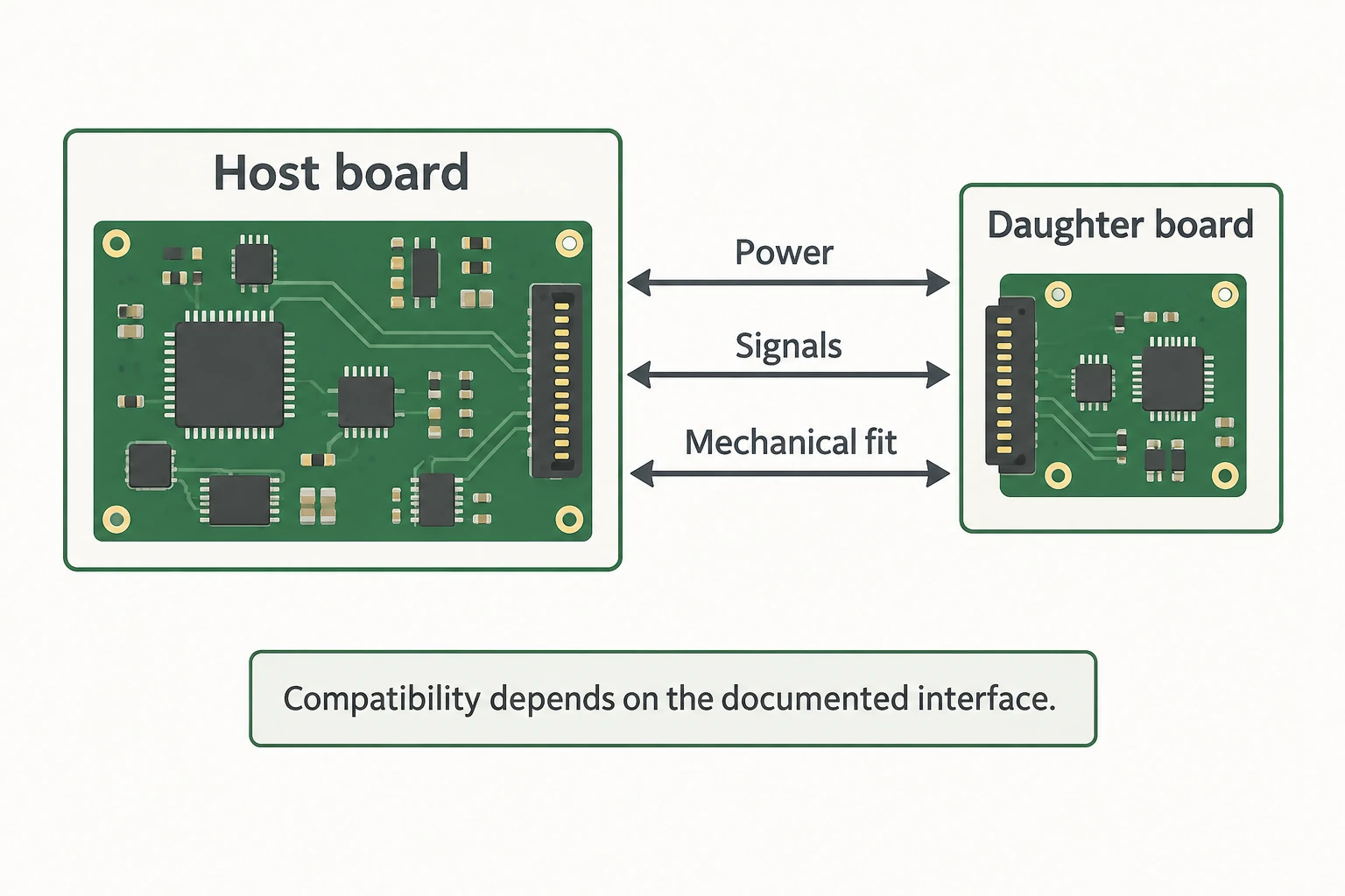
Physical fit is only one compatibility check
Start with the exact board identifiers and revisions. A familiar connector shell or matching outline is a useful observation, but it leaves the signal assignment, voltage requirements and supported operation unresolved.
A practical compatibility record has three groups. Mechanical information includes the connector, orientation, mounting arrangement and clearance. Electrical information includes the documented power and signal interface. Software information includes the supported controller, firmware or application where required.
Analog Devices’ SDP documentation illustrates the software side of the relationship: evaluation software is specific to the relevant daughterboard, and controller compatibility is explicitly documented. A statement about compatibility in one direction does not necessarily establish the reverse. Check the particular combination listed by the manufacturer.
Why an adapter is not automatic proof of compatibility
An adapter or interposer may route signals from one connection to another. That description alone does not prove that it changes voltage levels, supplies missing power, implements a protocol or makes unsupported software work. Its documented function determines what it solves.
When an adapter appears in a proposed combination, include its identifier in the compatibility record. The assembly is then a host–adapter–daughterboard combination, not merely a pair of boards. This makes the evidence easier to review and prevents a necessary intermediate part from disappearing from a purchasing request.
Do not infer permission for powered insertion from the word “daughterboard.” Follow the manufacturer’s connection and power-state instructions for the specific system. This article identifies the information needed; it does not provide a generic connection procedure.
Identify, store and hand off the correct assembly
Keep the board part number, revision, intended host and known configuration together. Record whether the item is an individual board, a tested combination or a replacement awaiting verification. Those statuses answer different questions for an engineering team.
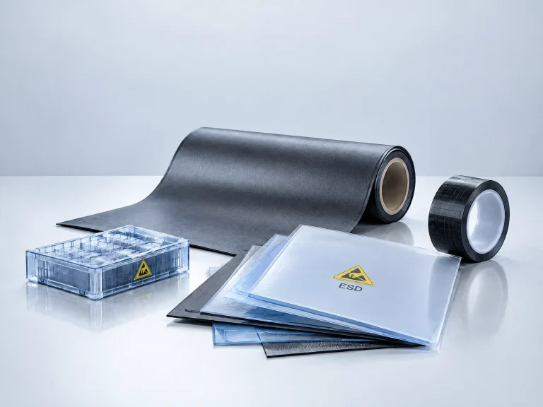
For physical handling, include connector height, underside components and intended support points when assessing a Quan Dun ESD tray. A generic photograph cannot establish that a tray fits a particular daughterboard. The actual assembly dimensions and handling requirements should guide the selection.
The most useful identification is therefore more specific than “a small board attached to a bigger one”: it names the function, the intended host and the documented interface that makes the combination work.