

An SPDT switch is a single-pole, double-throw switch: one common contact can connect to either of two alternative contacts. That describes its electrical arrangement. It does not tell you whether the switch has a center-off position, returns when released, or uses a particular physical terminal order.
By ZiroSip · October 25, 2026
For selection, separate three questions: which contacts connect, how the actuator behaves, and which conditions the exact part is rated for. A familiar three-terminal body answers none of those questions completely without its circuit diagram and full part number.
What an SPDT switch connects
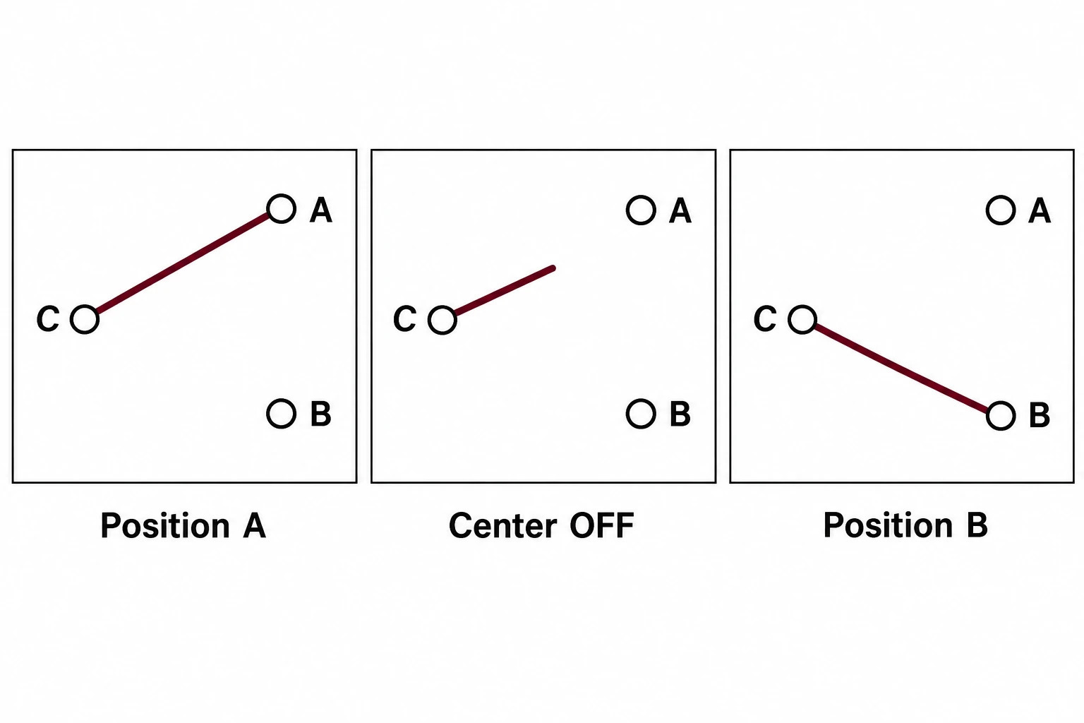
The common contact is the shared part of the selectable path. The throws are the alternative contacts it can reach. In the conceptual example below, C means common and A and B identify the two throws. These letters are explanatory labels, not a manufacturer’s pin numbers.
| Contact state | C to A | C to B | Meaning |
|---|---|---|---|
| Position A | Connected | Open | The common selects A |
| Center OFF, where provided | Open | Open | Neither throw is selected |
| Position B | Open | Connected | The common selects B |
The middle row belongs only to a version with a specified center-off position. A two-position ON-ON switch does not acquire a stable OFF position merely because its moving contact travels between the throws.
SPST, SPDT and DPDT describe different arrangements
SPST means single pole, single throw: a simple contact path is opened or closed. SPDT adds a second alternative throw for the common contact. DPDT means double pole, double throw, with two changeover contact groups operated by one actuator. Choose the arrangement from the required contact states rather than from the number of visible actuator positions.
A useful specification records the intended states in words before choosing a catalogue abbreviation. For example, “select path A or path B, with no stable disconnected state” is a more complete requirement than “small toggle.” The first statement can be checked against a contact table; the second describes appearance.
Read ON-ON, ON-OFF-ON and momentary notation
ON-ON normally describes two selectable connected positions. ON-OFF-ON adds a center position in which the common connects to neither throw. Manufacturers may display ON-ON as ON-NONE-ON in a three-column catalogue table; NONE means that no center position is provided.
Momentary action is a separate characteristic. A momentary actuator returns when released, while a maintained actuator stays in its selected position until operated again. In the cited toggle catalogue, parentheses identify a momentary position, as in (ON)-OFF-(ON). Confirm that convention in the selected manufacturer’s documentation.
| Example function | What to establish | Selection consequence |
|---|---|---|
| ON-ON | Two maintained connected positions | Use when the selection should stay where placed |
| ON-OFF-ON | Two connected positions plus a stable center OFF | Use when the task also needs neither path selected |
| (ON)-OFF-(ON) | Two momentary connected positions returning to OFF | Use when selection should last only while held |
| Mixed maintained/momentary | Which position returns and where it returns | Record the complete function, including parentheses |
Do not remove parentheses or the middle column when transferring a supplier’s description into a purchase order. A short description that drops the return action can make two different functions look identical.
Toggle and rocker describe the interface
An SPDT toggle switch uses a lever as its actuator. An SPDT rocker switch uses a rocking actuator. The shape can suit a particular panel or operator, but it does not replace the electrical function specification. The selected version still needs the required contact states and action.
For a replacement, compare the mechanical drawing alongside the contact diagram. Relevant drawing questions include the mounting format, panel opening, available clearance, actuator travel, terminal style and orientation. Record the exact drawing revision used for that comparison.
The cover shows generic toggle and rocker forms. Their appearance illustrates the interface choice; it does not establish an internal circuit or a compatible part number.
Identify the common from the correct drawing view
Use the exact part’s terminal identification and the drawing’s stated viewing direction. A contact diagram, an actuator-side view and a terminal-side view serve different purposes. Do not transfer the left-to-right order of a generic sketch directly onto the underside of a real switch.
For Series A, the cited toggle catalogue notes that the diagram’s terminal numbers do not appear on the switch itself. That is a practical reason to retain the drawing rather than rely on markings that may not exist. It is also why “the middle pin is common” is an inadequate universal replacement instruction.
For a document-based comparison, put the required contact state beside the manufacturer’s connected-terminal entry. If the two cannot be mapped unambiguously, mark the mapping unresolved and obtain the supplier’s confirmation.
Check transitions separately from stable positions
A state table describes the selected positions, not every event during movement. Break-before-make means the previous contact path opens before the next path closes. The SPDT abbreviation alone does not establish the selected device’s transition sequence; use its specified contact action when the application depends on that sequence.
Mechanical contact bounce is another consideration. Contacts may make and break repeatedly during a transition before settling. A digital input can therefore observe several transitions from one actuator movement. This is different from choosing ON-ON or center-off, and a stable-state diagram cannot provide a debounce time.
In a design review, keep the stable contact function, transition requirement and input interpretation in separate fields. The switch supplier can identify the specified contact sequence; the circuit or firmware designer can define how an input event should be recognized. No generic timing value should be added to the purchase specification without that design basis.
Build a complete selection record
The following proposed checklist connects a required operator action to an exact orderable configuration. It organizes the comparison rather than approving a device for an unspecified circuit:
- Contact arrangement: the required common/throw paths and any center-off state.
- Actuation: maintained, momentary or mixed action, including the return position.
- Transition: the required contact sequence, where relevant.
- Electrical duty: the manufacturer’s voltage, current and application conditions for the exact version.
- Mechanical fit: mounting, clearances, actuator and terminal drawing.
- Order identity: manufacturer, complete part number, suffixes and document revision.
Electrical ratings need their own review. Do not infer a DC rating from an AC value, or a suitable load duty from physical size. The record should retain the manufacturer’s stated conditions rather than replacing them with a general percentage margin.
Example: matching size without matching function
Suppose a panel needs two maintained selections and a maintained center OFF. A proposed substitute has the same mounting opening but is specified ON-NONE-ON. It does not meet the stated center-off requirement, even if the lever and terminals look similar.
A second proposal has the center OFF but uses momentary end positions. That also changes the requested operator action. The useful next step is a precise supplier question: which complete configuration provides the required contact states and maintained action within the documented mounting arrangement?
Keep the accepted contact table and mechanical drawing with that configuration. A later suffix change can then be checked against the specific requirement it affects.
References
- Same Sky: Fundamentals of Switches — pole/throw terminology, actuation and selection characteristics.
- NKK Switches: toggle catalogue — Series A, POLES & CIRCUITS table, function notation and drawing views.
- VCC: SPDT configurations and applications — contact transitions and mechanical contact bounce.