

An alternating current contactor is an electrically operated switch used to connect and disconnect an AC load. A coil moves a contact mechanism; the main contacts switch the load circuit. Selecting a suitable device requires separate checks of the load duty, the coil’s control supply and the surrounding control-and-protection arrangement.
By ZiroSip · October 25, 2026
The useful starting point is the manufacturer’s complete part number and datasheet. “AC contactor” alone does not tell you the coil voltage, whether its coil accepts AC or DC, or which load conditions its contact ratings describe. This guide explains those distinctions for specification and purchasing; it does not provide wiring or energized-testing instructions.
How an alternating current contactor operates
In a conventional electromechanical contactor, energizing the coil creates magnetic force that moves an armature. That motion operates the contacts. For a conventional non-latching device with normally open main contacts, releasing the coil allows the return mechanism to open those contacts again.
The main contacts and auxiliary contacts have different jobs. Main contacts switch the intended power load. Auxiliary contacts, when provided, serve control or indication functions. Their contact arrangement and ratings need their own identification; an auxiliary contact is not simply an extra main power pole.
Manufacturers offer contactors for applications including motor-driven equipment, heating and air-handling systems. The application name helps locate a product family, but the actual duty and control requirements determine which entry in that family is relevant.
Read the coil and load ratings separately
The contactor contains a control function and a load-switching function. Their ratings answer different questions, even when they appear on the same device. Keep them in separate fields when preparing a specification.
| Specification field | What it describes | What it cannot establish by itself |
|---|---|---|
| Coil supply | The specified voltage or range, AC/DC type and applicable frequency | The load the main contacts can switch |
| Main-circuit voltage | The operating-voltage condition for the load rating | The supply required by the coil |
| Operational current and duty | The contact rating under the stated load conditions | A universal rating for every application |
| Main-pole arrangement | The switched power-contact configuration | The auxiliary-contact arrangement |
| Auxiliary contacts | The control/indication contacts and their ratings | Approval to carry the main load |
An AC load does not mean that every compatible contactor has an AC-only coil. The cited coil-code guidance includes conventional AC and DC versions as well as electronic coils with specified AC/DC supply ranges. The accepted supply is a property of the exact coil or assembly, not something to infer from the phrase “AC contactor.”
Coil suffixes also need the relevant manufacturer’s decoding table. A suffix that identifies voltage and frequency in one product family should not be treated as a universal industry code. Retain the full suffix when copying a part number into a purchasing request.
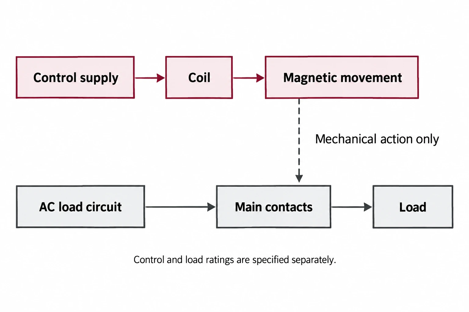
A concise rating card should therefore place “control supply” beside “load duty,” with a source document for each. If either field remains unknown, the card is incomplete even when the device’s appearance and mounting dimensions seem familiar.
AC-1, AC-3 and AC-4 describe different duties
A utilization category describes the kind of load and switching duty behind a rating. It is not another name for the coil supply. The cited US guidance distinguishes AC-1 duties involving non-inductive or slightly inductive loads from AC-3 squirrel-cage motor starting and interruption during normal running.
The cited catalogue also identifies AC-4 with duties including plugging and inching. Plugging involves counter-current braking or reversal, while inching involves repeated short motor movements. These conditions should not be silently treated as ordinary running interruption.
| Category | Duty context | Question for the datasheet review |
|---|---|---|
| AC-1 | Non-inductive or slightly inductive loads, such as resistive heating | Is the quoted current specifically an AC-1 rating? |
| AC-3 | Squirrel-cage motor starting and switching off during normal running | Does the manufacturer’s motor-duty rating cover this application? |
| AC-4 | More demanding motor switching such as plugging or inching | Has the actual operating sequence been assessed? |
For an AC contactor for motor control, a catalogue’s largest current figure is not a sufficient selection rule. Ask which voltage, utilization category and operating conditions accompany that figure. When comparing quotations, put those conditions in adjacent columns so a resistive-load rating is not mistaken for the required motor-duty rating.
What is the difference between a relay and a contactor?
The names overlap in electromechanical switching. Contactors are commonly specified for power-load duties, while relays cover a broad range of switching and control tasks. The cited catalogue lists separate duty categories for contactors and contactor relays. That is a useful reason to compare the stated application rather than treat a fixed current threshold as a complete definition.
For a purchasing decision, compare the exact rated duty, contact arrangement and manufacturer’s stated application. A power relay with a familiar current figure should not be accepted as a contactor substitute solely on that figure. Conversely, the word “contactor” is not enough to establish compatibility with a particular controller or load.
Switching and protection remain separate functions
A contactor does not, by itself, provide motor overload or short-circuit protection. The cited catalogue describes a starter as a contactor plus overload protection, with a separate short-circuit protective device in the coordinated arrangement. The complete equipment design determines how those devices work together.
Keep the switching-device selection and protection review as separate lines in the project record. A replacement request should identify the existing arrangement and go to the responsible engineer or manufacturer for approval; this component overview does not determine protective-device sizes or settings.
Build a replacement request that preserves the important details
A useful replacement request lets the reviewer compare two defined configurations. A photograph of the front face can help identify the device, but it should accompany the complete part number and relevant documentation rather than replace them. The following is a proposed handoff checklist for records already available from drawings, purchasing files or equipment documentation.
- Exact identity: manufacturer, full assembly number, coil suffix and attached accessory numbers.
- Control supply: documented voltage or range, AC/DC type and applicable frequency.
- Load duty: application, operating voltage, load information and the stated utilization category.
- Contact arrangement: main-pole configuration and required auxiliary normally open/normally closed contacts.
- Physical arrangement: documented dimensions, mounting, terminals and accessory interfaces.
- Operating conditions: the documented switching sequence, environment and any manufacturer conditions relevant to the quoted rating.
- Approval record: the proposed substitute, its datasheet revision and the responsible reviewer’s decision.
Mark missing fields as unresolved instead of filling them from a visually similar listing. That makes the request actionable: the reviewer can ask for the particular missing coil or duty information without restarting identification from scratch.
Example: two quotations that share only a current figure
Suppose a maintenance buyer receives two proposed substitutes described with the same headline current. One quotation gives only an AC-1 value. The other provides a motor-duty value but leaves the coil suffix unspecified. Neither quotation yet establishes a matching replacement.
The buyer can return a focused request: provide the rating at the required duty and operating voltage, identify the exact coil supply, and confirm the main and auxiliary contact arrangement. This is a comparison procedure, not a recommendation to choose either hypothetical device.
Once the missing data arrives, preserve the documents used for the comparison. Record which fields match, which differ and who accepted each difference. If the supplier later changes the offered suffix or accessories, that record identifies the part of the comparison that needs review again.
Use the datasheet to close the selection
A complete selection record connects the intended switching task to an exact device configuration. It should identify the load-duty rating, control supply, contact arrangement and physical requirements, while leaving system protection and installation to the appropriate equipment-design review.
That record is more useful than a generic “same amperage” replacement note. It gives purchasing, maintenance and engineering a common description of what is being supplied and which application conditions the approval actually covers.
References
- Schneider Electric: magnetic contactor operation and components — electromagnetic actuation, main contacts and auxiliary contacts.
- Schneider Electric: contactor and relay coil voltage codes — supply type, frequency and specified electronic-coil ranges.
- Schneider Electric USA: AC-1 and AC-3 — load-duty distinctions.
- ABB: contactors and overload relays catalogue — pp. 152 and 158: separate protection functions and utilization categories.