

A QR code PCB marking connects a physical circuit board to an identifier, document or production record. A useful implementation needs both a readable symbol and a reliable answer to one question: which board does this scan identify? Start with the intended reader and identity scheme, then allocate the marking area and validate the complete journey through production.
By ZiroSip · October 25, 2026
Decide what the board code identifies
A part number, revision, manufacturing lot and individual serial number describe different things. Before generating artwork, decide whether the code identifies a design, a group of boards or one physical assembly. That decision determines what the receiving system should return after a scan.
For example, a proposed board record might use BOARD-B017 as its stable identity, with revision and inspection status stored in the associated record. The example is a workflow design, not an existing customer record. Its advantage is that an inspection result can change without requiring the board’s identity to change.
| Purpose | Proposed encoded content | What the application should resolve |
|---|---|---|
| Open controlled documentation | A maintained document URL or document key | The applicable document and revision |
| Track a manufacturing lot | A lot identifier | The correct group of boards |
| Track an individual board | A unique board identifier | One physical board’s record |
| Track a removable tray | A separate carrier identifier | The carrier and its current contents |
Keep carrier identity separate from board identity. A tray label can help locate a batch, but it does not prove which individual board was inspected after boards move between carriers. A proposed traceability record should therefore preserve the relationship between board, carrier and processing event rather than treating them as interchangeable identifiers.
Check whether the symbol is actually QR
A square mark on a PCB may be Data Matrix rather than QR. Both are two-dimensional code formats used for identification, but they are not the same symbology. Ordinary QR symbols have prominent square finder patterns near three corners. Confirm the chosen format in the drawing and reader configuration instead of naming every square code “QR.”
For a PCB QR code intended to open documentation, test the intended phone or reader. For an internal serialization workflow, ask the production team which symbology its scanners and software accept. The destination and available board space matter more than which code looks familiar.
QR code PCB layout: reserve the complete reading area
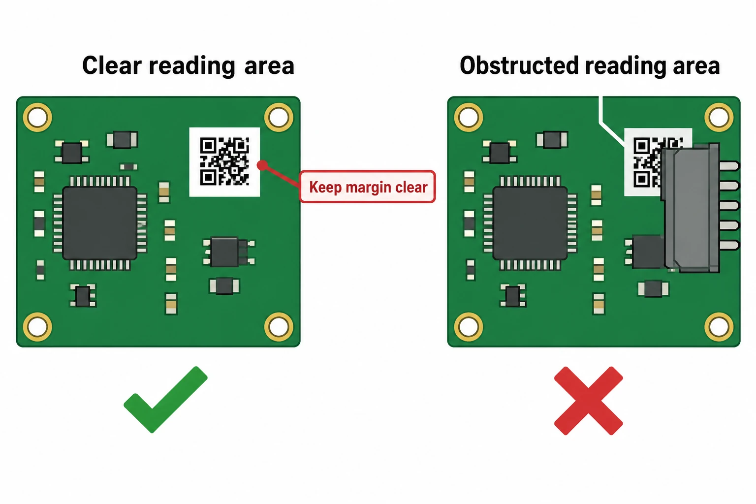
The small squares inside a QR symbol are called modules. DENSO WAVE specifies a clear margin, or quiet zone, four modules wide on every side of an ordinary QR Code. Include that margin in the reserved footprint; the patterned square alone is not the complete area.
If the symbol is N modules across and each module has side length m, the complete side length is (N + 8) × m. The extra eight accounts for the two opposite four-module margins. This calculation describes QR geometry; it does not establish the smallest code a particular PCB process can reproduce.
Module size also needs to match the reader. DENSO’s guidance considers both marking resolution and scanner resolution. A fabricator’s ability to reproduce a small feature is only part of the decision; the actual camera and reading conditions must resolve it too. Avoid specifying a universal minimum millimeter size without those inputs.
Review access after the board is populated
Reserve the location in the assembled-board view, not only the bare-board artwork. As a placement review, check the following questions with the assembly and inspection teams:
- Visibility: will a connector, shield or later assembly cover the mark?
- Clear space: do reference text, borders or other markings enter the reserved margin?
- Reading position: can the intended station see the code in its actual fixture or tray?
- Process sequence: when is the identity applied, and at which later stages will it be read?
- Marking method: which proposed label, printed or direct-mark process will the supplier qualify for this board?
These questions form a proposed acceptance review. They do not mean that a particular ink, label or laser process has already been qualified. Put the agreed location and method in the controlled drawing so that the marking supplier and reader integrator work from the same requirements.
Separate decoding, data validation and quality verification
A successful scan tells you that one reader decoded that symbol under those conditions. It does not, by itself, prove the identifier is correctly formatted, belongs to the board in front of you or meets an agreed symbol-quality criterion.
Cognex distinguishes data validation from barcode verification. Validation checks encoded-data formatting; verification evaluates the quality of the mark using defined measurement conditions. Keep those checks separate from the production application’s additional job of retrieving the correct record.
| Check | Question to answer | Evidence to retain |
|---|---|---|
| Decode | Did the intended reader return the payload? | Raw decoded value and station identity |
| Data format | Does that value follow the approved identifier format? | Format-validation result |
| Record mapping | Does the value retrieve the intended board and revision? | Resolved record and comparison result |
| Identity uniqueness | Could another board carry the same individual ID? | Duplicate-detection result |
| Symbol quality | Does the mark meet the agreed quality criterion? | The applicable verifier report when specified |
Agree on the required evidence before a production release. A reader’s successful decode should not be recorded as a verifier grade. Equally, a good-quality symbol does not fix a database that associates its payload with the wrong assembly.
Run a pilot that follows the physical board
A useful pilot starts with a deliberately small, controlled set of board identities. Assign the proposed identifiers, compare the artwork or marking data with the approved list, and inspect the physical marks. Then scan at the stations where the identity will actually be used.
At each station, record the decoded value before any application transforms it. Compare the retrieved record with the expected physical board, design revision and processing event. Include a rejected or unreadable sample in the procedure so the team can check how the software handles a failure rather than only a successful read.
For a workflow trial, the following record is enough to expose several different problems without pretending to be a complete manufacturing execution system:
- Expected identity: the approved board identifier and revision.
- Observation: station, process stage, reader and raw decoded value.
- Application result: resolved record, duplicate check and processing status.
- Disposition: accepted, held or rejected, with an owner for the discrepancy.
Record failed scans as observations in their own right. Repeatedly scanning until the application accepts an entry can hide the distinction between a difficult mark and an incorrect record. The pilot should preserve that distinction so the responsible team can investigate the right part of the workflow.
Diagnose the failing layer before changing the artwork
If no payload returns, examine the physical mark, reserved margin, visibility and reader configuration. If the payload returns but fails validation, compare the encoded content with the agreed format. If the value is valid but opens the wrong record, investigate identifier assignment and application mapping. These are proposed troubleshooting branches, not interchangeable reasons to enlarge every code.
When the pilot succeeds, retain its approved drawing, payload convention, reader setup and acceptance criteria together. A later change to one of those inputs gives the team a clear reason to repeat the affected checks.
Keep the mark usable during board handling
If scanning happens while boards remain in a carrier, assess the marked face and reading access alongside the board’s support requirements. Quandun’s ESD tray range is a starting point for physical handling options; the actual tray configuration still needs to fit the assembly and its handling route.
Code readability, carrier identity and ESD suitability remain separate acceptance questions. The final handoff should name the physical board, the record it resolves to and the agreed way to read it at each processing stage.
References
- DENSO WAVE: determining the QR code area — symbol footprint and four-module quiet zone.
- DENSO WAVE: setting module size — marking and reader resolution.
- NCAB Group: PCB information and traceability codes — QR and Data Matrix identification context.
- Cognex: Introduction to Barcode Verification — differences between reading, data validation and quality verification.