
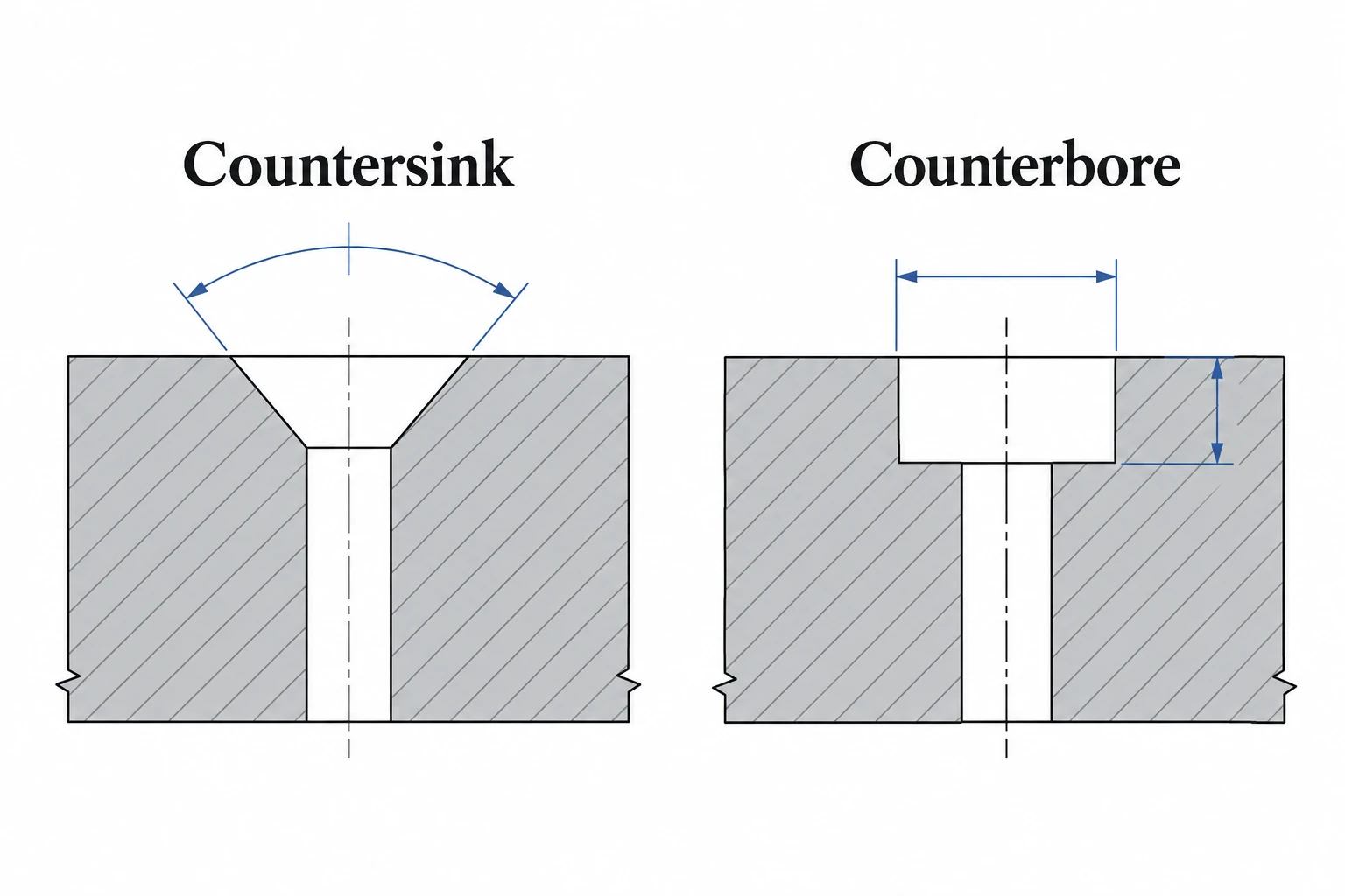
Countersink vs counterbore comes down to the shape of the recess around a hole. A countersink is conical and supports a matching countersunk fastener head. A counterbore is cylindrical, with a flat shoulder that can accommodate a suitable flat-bearing head. Both can help recess a fastener, but they are not interchangeable geometries.
Choose the fastener and the required seating condition before completing the hole callout. “Make the screw flush” describes a goal, but it does not provide enough information to manufacture or inspect the feature.
Countersink vs counterbore: the geometry
| Feature | Countersink | Counterbore |
|---|---|---|
| Upper recess | Conical | Cylindrical |
| Head seating surface | Angled surface | Flat shoulder |
| Typical matching head | Compatible countersunk head | Compatible cylindrical or other flat-bearing head |
| Key recess description | Diameter and included angle | Diameter and depth |
| Separate information | Underlying hole and its purpose | Underlying hole and its purpose |
A top view may show similar concentric circles for both features. A section view makes the difference much clearer: the countersink slopes toward the smaller hole, while the counterbore has a step with a flat seating surface. This distinction matters when a quotation is based on a drawing rather than a physical sample.
Match the bearing surface, not just the visible head
The underside of the fastener head determines how it bears on the recess. A conical head needs a compatible seating angle; a flat-bearing head needs its intended support. A recess that merely looks large enough in a photograph does not establish that relationship.
The designer should also define whether the head is flush, below the surface or intentionally proud. These are different acceptance conditions. Record the chosen fastener part or standard alongside the drawing, so a later fastener change does not silently change the seating requirement.
There is no universal winning feature. Selection depends on the joint, available material, access and required geometry. Neither a countersink nor a counterbore establishes a joint’s strength simply by being present.
What belongs in the drawing callout?
For a countersink, identify the underlying hole and specify the recess diameter and included angle, together with the applicable tolerances. For a counterbore, identify the underlying hole and specify the counterbore diameter and depth. Add the number and locations of repeated features through the drawing’s normal dimensioning scheme.
Do not infer the underlying hole’s role from the recess. A clearance hole, a threaded feature and a different assembly arrangement have different requirements. A complete drawing keeps the recess description and the underlying hole description understandable together.
The countersink symbol is commonly shown as a V-shaped mark, while the counterbore symbol resembles a squared U. Symbols can render poorly when drawings are copied into email or spreadsheets. Retain the released drawing or an unambiguous written description instead of relying on a pasted symbol alone.
Counterbore and spotface are not the same request
A spotface provides a shallow flat seating area. A counterbore generally creates a deeper recess to accommodate a head or related feature. Xometry describes this difference in the purpose and depth of the upper cavity.
If the requirement is only to establish a flat seat, asking for a deep counterbore may add an unintended feature. Conversely, a spotface description does not necessarily provide enough depth for a recessed screw head. State the seating task explicitly before finalizing dimensions.
Material and process still affect manufacturability
Protolabs distinguishes cut and formed countersinks in its sheet-metal guidance. That is a useful reminder that similar finished appearances can arise from different manufacturing operations. The supplier’s stated tolerance capability must apply to the chosen process and feature.
A practical request contains the released drawing revision, material and thickness, fastener identification, required head position and acceptance dimensions. If the supplier proposes a process change, compare the resulting feature with those requirements rather than approving it from its name alone.
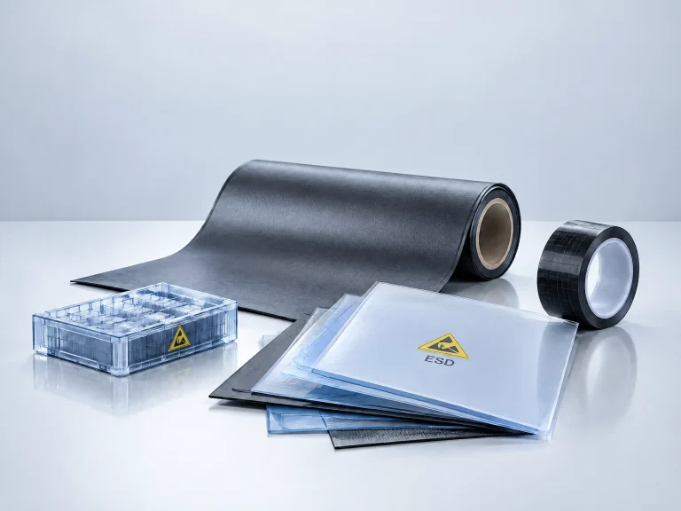
For an electronics assembly, verify that the completed fastening arrangement also fits its handling support. Quan Dun’s ESD tray options should be evaluated against the assembly’s actual protrusions and contact areas. That handling check is separate from machining or approving the hole feature.