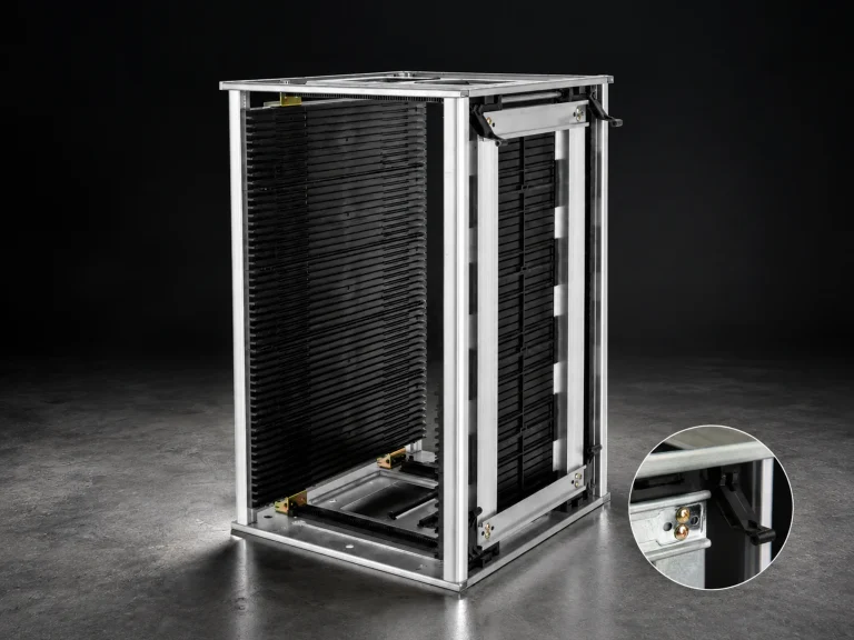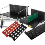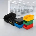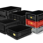


ESD racks for PCB and electronics handling should be selected from the board, tray, or container they must support. Slot width, pitch, groove depth, access direction, route, and configuration evidence all matter. The phrase “ESD rack” alone does not identify a suitable geometry.
The CH-ESD ESD Rack family provides several rack formats. Use the category to find a candidate family, then verify the named model against the actual PCB or tray and movement route.
1. Identify the object ESD racks must hold
A rack for bare boards has a different support problem from a rack for trays, magazines, or component containers. Record the object’s length, width, thickness, edge condition, handling orientation, and whether operators remove one item or a group at a time.
The CH-ESD rack pages show model variation. One page lists QD-9805407, QD-9805408, and QD-9805409 with different groove and slot information. Another lists QD-9805403, QD-9805404, and QD-9805405 with shallow/deep groove options. These values help structure the request, but they do not make one model a universal fit.
| Rack question | Required input |
|---|---|
| What is stored? | PCB, board, tray, magazine, or component container. |
| How is it supported? | Edge contact, groove, separator, base, or adjustable support. |
| How is it removed? | Top, front, side, one-at-a-time, or batch handling. |
Use a representative board or tray to verify the complete support path. Check the entry angle, contact points, component clearance, connector overhang, and the hand space needed at the normal workstation. An ESD PCB rack that accepts the nominal board thickness can still interfere with mounted components or make controlled removal difficult.
Capacity should be defined as usable positions for the approved object, not only the slot count printed on a page. Wider parts, separators, labels, or keep-out spaces can reduce the practical capacity. Record which positions are allowed and how operators identify a blocked or quarantined position. During the trial, load the lowest, highest, and most difficult-to-reach positions with representative parts. Confirm that the rack remains accessible at the intended shelf or station and that labels stay visible when neighboring positions are occupied. Save the accepted rack setting, object orientation, and position map with the model request.
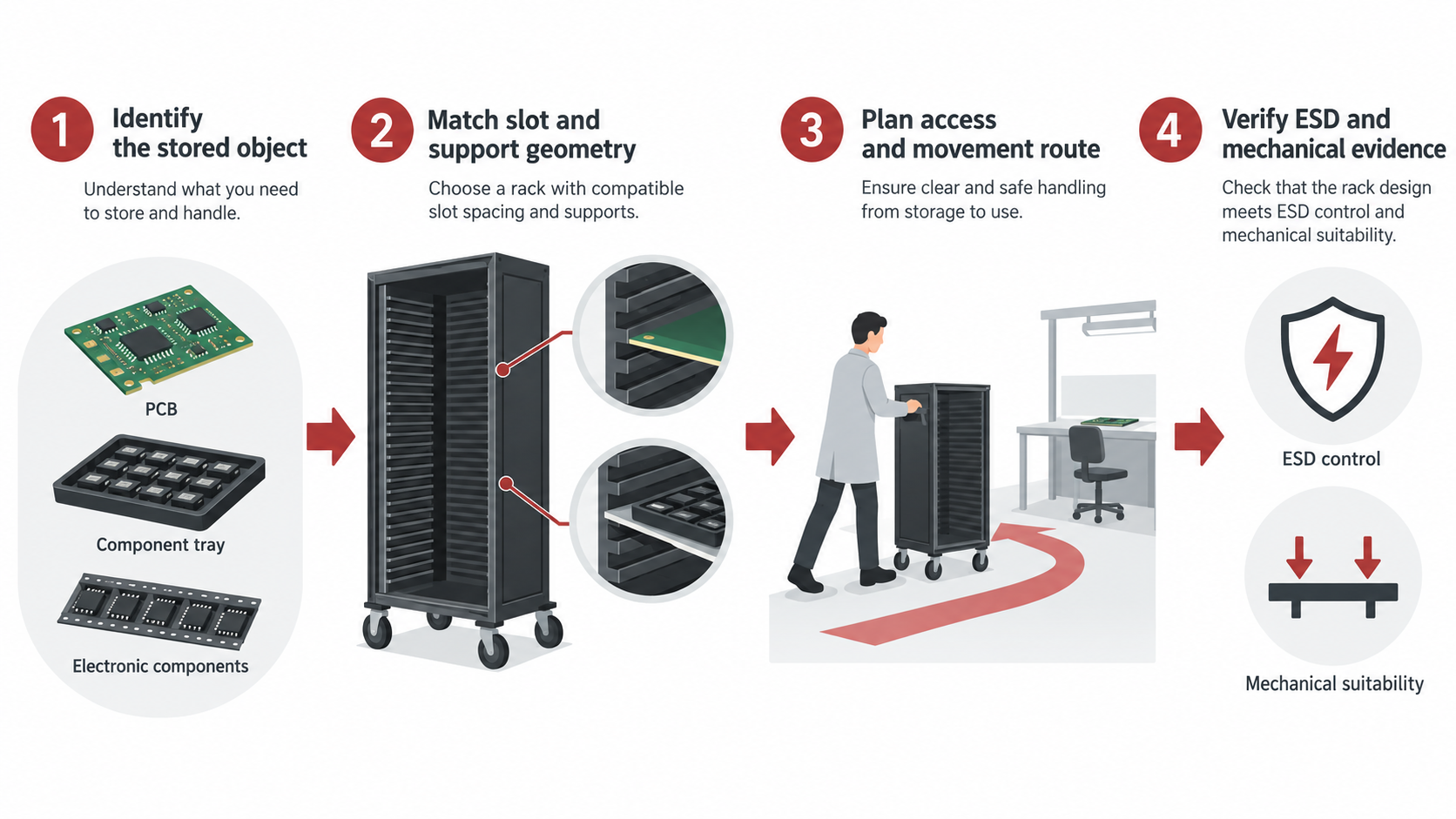
2. Match slot geometry to the actual part
Slot width, pitch, and groove depth determine whether the object is supported, separated, and removable. Too little clearance can create insertion damage or slow picking. Too much clearance can allow movement, leaning, or contact between adjacent boards.
Ask for a drawing or a model-specific table that shows the groove and slot geometry. Do not infer a rack’s usable pitch from its product title, photograph, or a different model in the same family.
For adjustable ESD storage racks, define the approved adjustment range and the method used to lock or repeat the setting. A trial setup should confirm that the supports remain aligned and that the board cannot enter a neighboring position during loading.
3. Plan access, storage, and movement as one route
A fixed rack at a line-side station prioritizes repeatable access and clear identification. A warehouse rack may prioritize density, replenishment, and separation by lot or status. A rack used during transfer needs a stable support method and a route that does not force operators to remove boards in an uncontrolled location.
- Define the normal reach direction and the maximum number of positions opened at once.
- Mark how empty, quarantined, inspected, and released positions are identified.
- Confirm whether the rack stays in an EPA or moves between controlled areas.
4. Connect rack selection to the ESD-control program
EOS/ESD guidance describes material-handling containers inside an EPA as low charging and dissipative or conductive. Outside the EPA, packaging also needs discharge shielding. A rack may support organization and handling, but its ESD role still depends on the material, configuration, location, and handling conditions.
Ask the supplier to identify the material classification, test basis, measurement conditions, and scope of any static-index value. Keep the rack evidence connected to the actual model and the route in which it will be used.
If the purchasing language uses “anti static rack,” clarify whether it means low-charging behavior, a conductive or dissipative material, a grounding arrangement, or a complete packaging function. The requested evidence should use the terminology of the site’s ESD-control program and the offered configuration.
5. Send a model-ready rack request
- Stored object: board, tray, magazine, or container; size, thickness, edge condition, and quantity.
- Geometry: groove width/depth, pitch, slot count, support points, clearance, and adjustment range.
- Route: shelf, line-side station, cart, receiving, warehouse, and movement between departments.
- Organization: labels, lot separation, status identification, replenishment, and inspection access.
- ESD evidence: material classification, test method or test basis, applicable documentation, and conditions on the result.
Review the ESD Rack family after defining the use case
Start with the ESD Rack category, then compare the model-specific information on the ESD Safe Rack or the PCB and board storage rack page. If the normal object is a magazine rather than a board or tray, use the separate ESD Magazine Rack route.
References
- EOS/ESD Association: ESD Fundamentals, Part 3 — packaging and material-handling container context inside and outside an EPA.
- EOS/ESD Association: ANSI/ESD S541-2026 — packaging properties and evaluation context for production, transport, and storage.
- IEC 61340-5-1:2024 — general ESD control-program requirements for organizations handling electronic parts.