

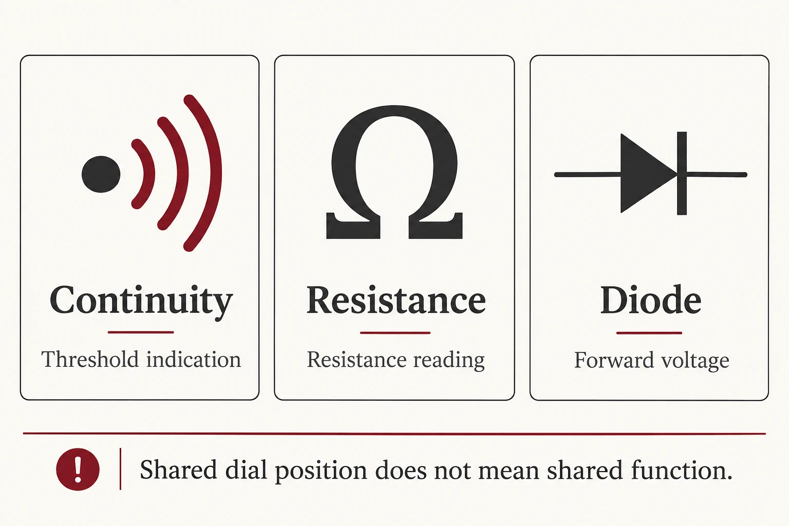
The continuity test symbol on a multimeter usually looks like a small buzzer or a set of curved sound-wave lines. It identifies the mode that gives an audible indication when the measured resistance meets the meter’s continuity threshold. The symbol may share a dial position with the ohm sign, Ω, or the diode symbol. A shared position does not mean those functions are interchangeable.
Read the active display indicator as well as the dial. On a meter with a shared function, turning the selector may leave resistance or diode mode active until a function button changes it. The instrument’s own manual is the reference for that control sequence.
Continuity test symbol versus resistance and diode symbols
These three markings answer different questions. A continuity indicator reports whether a threshold condition is met; a resistance display gives a resistance value; diode mode commonly displays forward voltage drop. The number on the screen only makes sense after you identify the selected function and its units.
| Marking | What to look for | Meaning of the selected mode |
|---|---|---|
| Continuity / buzzer | Curved sound-wave lines or a buzzer icon | Audible indication associated with a resistance threshold |
| Resistance | Ω, sometimes with a range multiplier | Resistance measurement, without assuming the beeper is enabled |
| Diode | An arrowhead-like mark pointing toward a short bar. The continuity icon usually shows curved sound waves. | Diode test, commonly showing forward voltage drop |
For example, an ohm symbol beside the rotary switch is not enough to establish that an audible continuity function is selected. Conversely, a meter may show resistance while its continuity beeper is active. The screen and manual resolve the ambiguity better than a photograph of the dial alone.
Why the dial can show several functions together
Manufacturers use shared dial positions to give one control access to multiple functions. Fluke’s continuity guide explicitly describes a continuity setting combined with resistance and notes that some models require a separate button to activate continuity.
The practical question is therefore “Which function is active?” rather than “Which symbols are printed here?” Match the display icon to the function described in the manual. A button label, secondary symbol color or menu can help locate that instruction, but none should be treated as a universal convention across brands.
If the meter has no audible continuity feature, a resistance function does not acquire one simply because another model uses the same-looking dial. Check the exact model designation. This also avoids following instructions intended for a similar instrument with a different control layout.
What a beep or OL can tell you
A continuity beep is a threshold indication, not a general certificate that a component or circuit is good. The meter applies a small test current and evaluates the resulting resistance. A complete path can trigger the beeper even though that path does not meet the acceptance requirements of a particular assembly.
The threshold is not universal. A reading that triggers one meter’s beeper need not trigger another. Use the stated continuity behavior for the exact instrument rather than assigning a familiar number to every meter. The equipment’s acceptance limit is a separate requirement.
With separated probes, a meter in the appropriate mode may display OL. Here OL indicates an open or over-range condition: the resistance is beyond the function’s displayable range rather than a measured zero. The exact display meaning remains model- and function-specific. It should not be read as “zero resistance,” and the absence of a beep is not proof that a circuit is free of voltage.
Continuity is intended for de-energized circuits. Stored energy can remain after power is disconnected. This symbol guide does not provide live-circuit testing, capacitor-discharge or mains troubleshooting instructions; the equipment procedure and a competent person must establish the safe test condition.
A useful record separates the setting from the conclusion
When handing a question to a technician, record the meter model, selected function, displayed units and observed indication separately. A note saying only “it beeped” leaves out the information needed to interpret it. A photograph of the controls can help, provided the active display and exact model are identifiable.
Use three short entries: mode—the selected function; observation—the actual display or sound; acceptance requirement—the equipment document or test instruction that defines what counts as acceptable. If the third entry is unknown, record it as unknown rather than converting the first two into a pass.
For an electronics assembly, storage and handling remain a separate task. Quan Dun’s ESD trays provide component and PCB handling formats to compare by support geometry and part clearance. A tray choice cannot establish electrical continuity, and a continuity beep cannot qualify a tray’s ESD properties.
The most useful next step is an exact model manual and a clearly identified question: selecting the function, interpreting the display, or determining an application’s acceptance requirement. Keeping those questions separate prevents a familiar-looking icon from carrying more meaning than the instrument actually provides.