

Solder paste inspection (SPI) measures printed solder paste on a circuit board after stencil printing, usually before component placement. A 3D SPI system can evaluate properties such as deposit height, area, volume and position. The purpose is to identify printing conditions that need attention before the board continues through assembly.
The difficult part is interpreting the result. A measured quantity, an inspection rule and a process decision are three different things. A volume value tells you how much paste the system has measured relative to its reference. It does not, by itself, prove that a joint will be acceptable after reflow. This guide separates those decisions and provides a practical report structure for discussing a printing problem.
Where solder paste inspection belongs in the assembly process
The relevant sequence is stencil printing, paste inspection, component placement and reflow. SPI looks at the deposit while it is still accessible as printed paste. That timing gives the team a chance to review a print before adding components. Inspection later in the line answers different questions because the material and the assembly have changed.
Koh Young’s inspection overview describes SPI in relation to the printing step and explains the value of three-dimensional measurement. For a buyer or production engineer, the useful distinction is the inspection object: SPI examines the printed deposit. It is not a generic name for every check performed on an assembled PCB.
When reviewing a proposed inspection route, identify the decision each station must support. The SPI record should connect a deposit to its board location and printing reference. A later inspection record may connect a visible assembly condition to a component or joint. Keeping those records distinct makes it possible to investigate whether a concern began during printing or appeared at a later stage.
Height, area, volume and offset measure different things
Paste volume combines information about the deposit’s footprint and height profile. Area describes its measured footprint; height describes its vertical extent according to the system’s measurement method. Offset describes position relative to the defined target. Those quantities can change independently, so an acceptable-looking outline is not a complete volume assessment.
| SPI result | What it describes | Useful follow-up question |
|---|---|---|
| Area | The measured deposit footprint | Does the selected region and target geometry represent the intended deposit? |
| Height | The deposit’s vertical profile | Is the reference plane valid for this part of the board? |
| Volume | The measured three-dimensional quantity | What nominal volume and calculation basis is it compared with? |
| Offset / registration | Position relative to the programmed target | Is the target alignment correct, and is the shift local or repeated? |
| Bridge or smear indication | Paste geometry extending toward an unintended region | Does the image and region definition support the indicated condition? |
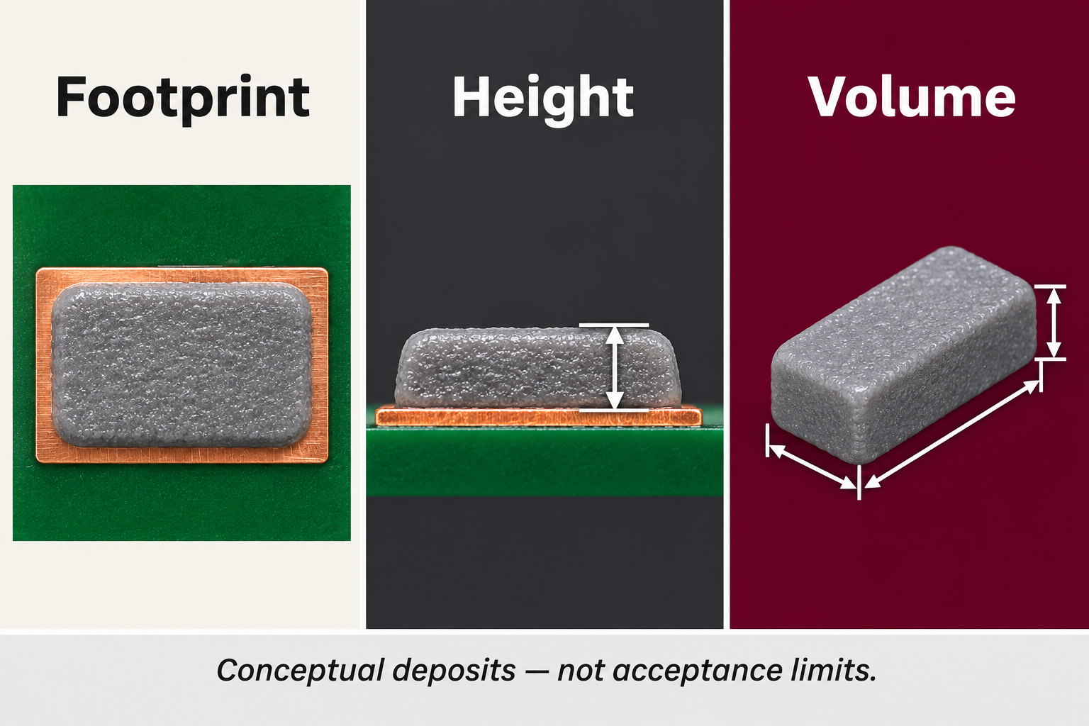
Koh Young’s overview lists volume, height, area and offset as distinct outputs. Its technology discussion also explains why board shape and the reference geometry matter. The resulting question is more precise than whether SPI passed: which quantity was evaluated, against which reference, at which location?
A worked paste-volume example, with its limits
Imagine a perfectly rectangular, uniform deposit measuring 1.0 mm long, 0.5 mm wide and 0.10 mm high. Its calculated volume is 1.0 × 0.5 × 0.10 = 0.05 mm³. These are hypothetical teaching dimensions, not a stencil recommendation, an inspection result or an acceptable amount of paste for a particular component.
If the footprint stays the same and the uniform height becomes 0.20 mm, the calculated volume becomes 0.10 mm³. That is twice the first value. If only the height were reviewed without the area, the reader would still lack part of the geometry. If only the footprint were reviewed, the two examples could appear equivalent from above.
A real deposit does not have to be a uniform box. Its top surface and edges can vary. A three-dimensional measurement evaluates the deposit shape rather than assuming that one convenient height multiplied by a nominal footprint fully represents it. Koh Young discusses this distinction in its explanation of paste-volume measurement.
Use the arithmetic to understand the relationship between quantities, then return to the actual inspection method. A production report should state the nominal reference, the measured quantity and the relevant units. Without that information, a percentage or a colored map can look conclusive while leaving the underlying comparison unclear.
SPI vs AOI: different inspection questions
SPI and automated optical inspection (AOI) are related inspection technologies, but their names do not make them interchangeable. SPI focuses on the printed paste stage. AOI can be used at other assembly stages to examine the relevant visible features. Modern AOI can also be three-dimensional; the distinction is not simply that SPI is 3D and AOI is always 2D.
| Inspection or test | Primary question in this comparison | What it does not establish alone |
|---|---|---|
| Pre-placement SPI | Does the printed deposit meet the defined geometry rules? | The completed assembly’s electrical behavior |
| Assembly AOI | Do the inspected visible features meet the programmed assembly rules? | Every hidden joint condition or every electrical function |
| Electrical testing | Does the assembly meet the selected electrical test requirements? | A complete history of the original paste geometry |
Inspection coverage depends on the actual equipment, program and process stage. A machine label is not a coverage statement. Ask which features the system evaluates, what the accepted reference is, and how a result is retained. That prevents a purchasing comparison from treating two differently placed inspection systems as equivalent simply because both produce a pass or fail.
For a process investigation, retain the connection between records rather than expecting one inspection station to answer every question. A paste result and an assembly result can support the same investigation without proving the same thing. This is especially useful when discussing a printing trend that does not appear identically in every later inspection image.
Interpret defects without inventing universal acceptance limits
An insufficient-volume indication means the result falls below the program’s defined criterion. An excessive-volume indication means it exceeds the corresponding criterion. Those labels are decisions made against configured limits. Their meaning depends on the correct job, target geometry, measurement basis and validated rules for that assembly.
There is no universal percentage window supplied by this guide. A number copied from another board or component can create a misleading comparison when its nominal reference differs. The process owner needs to define and validate the inspection rules for the actual design and manufacturing conditions, then control changes to those rules.
A useful review separates three fields: measured result, rule applied and disposition. For example, a report might identify a particular deposit as outside its configured volume criterion. The next decision is whether the program and reference are correct, whether the print needs process review, and what the authorized disposition is. The label alone does not identify the root cause.
This distinction also improves supplier discussions. Ask for the relevant deposit image, location, measured quantity and nominal reference before asking for a broad claim that the line has excellent SPI performance. A specific, traceable result can be investigated. A general inspection claim cannot explain which printing condition caused a concern or what change should be evaluated.
Separate measurement setup from a genuine printing change
A changed result can originate in the printed deposit, the measurement setup or both. Board alignment, the selected inspection region, the reference plane and the job revision affect how a result is interpreted. Koh Young describes active board-warpage compensation, illustrating why the board surface cannot always be treated as a perfectly flat reference.
Review the controlled program and board support before attributing every alarm to the printer. Conversely, do not dismiss a repeated trend as a measurement issue without evidence. Compare results from the same job and reference basis, retain their locations, and look for whether the condition is isolated or repeated across the relevant region or production interval.
A repeated position shift raises a different question from a volume change with stable position. A local height concern raises a different question from a board-wide reference change. These patterns help organize an investigation, but none uniquely proves a root cause. Keep the observed pattern separate from the proposed explanation in the report.
Koh Young’s inspection overview describes using inspection information in printing-process feedback. The practical requirement is traceability: know which measurement supported a proposed adjustment and retain the result after the authorized change. An unexplained adjustment that merely reduces alarms can hide the original issue if the program or reference was the part that needed correction.
Specify board support, handling and a traceable SPI report
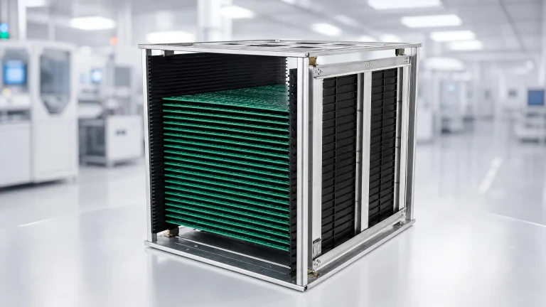
Board support and transport belong in the process review because the board must arrive in a suitable condition for the intended operation. A carrier must fit the board envelope and handling route. It should not be described as an SPI fixture unless that specific role and interface have actually been established.
CH-ESD’s ESD trays and component carriers are a starting point for reviewing storage and movement requirements. Confirm the support geometry, access and electrostatic requirements for the actual assembly. A handling carrier does not establish measurement accuracy, paste acceptance or compatibility with a particular inspection machine.
For a practical handoff, request the job and revision, board or panel identifier, deposit location, nominal-reference basis, measured height/area/volume/offset, rule applied, image, inspection time and authorized disposition. This is an original reporting worksheet: the fields connect a result to a decision without claiming that every machine exports the same file format.
Keep the original result with any later program or process revision. That record lets the next reviewer distinguish a corrected reference from a changed print. It also makes the supplier conversation more useful: the team can discuss a named deposit and decision instead of exchanging unrelated screenshots with no common reference.
Frequently asked questions
Can SPI replace the final assembly acceptance process? No. It supplies evidence about printed paste at its inspection stage. The assembly still needs the inspection and test coverage specified for the product. A good paste result is useful process evidence, not a complete functional or reliability verdict.
What should a buyer ask before comparing two SPI reports? Ask whether they use the same board revision, deposit locations, nominal references, units and decision rules. If those differ, first reconcile the definitions. Two percentages with different denominators are not a meaningful head-to-head comparison, even if their report layouts look identical.
References
- Koh Young: solder paste inspection technology — three-dimensional paste geometry and measurement context.
- Koh Young America: 3D inspection equipment — inspection stages and the roles of 3D inspection.
- EOS/ESD Association: basic control procedures and materials — handling controls for sensitive devices; not solder-paste acceptance criteria.