

A 120 ohm resistor has a nominal resistance of 120 Ω. Common identification examples include brown-red-brown-gold bands for a four-band ±5% part and the printed code 121 under the usual three-digit decimal system. The resistance value does not identify its power rating, package size or suitability for a particular circuit.
Readers often arrive here with two different tasks: identify a loose component, or understand why 120 Ω appears in a CAN network. This guide connects those tasks without treating them as the same decision. It includes marking examples, tolerance and power calculations, and the bounded meaning of two end-of-line resistors in a conventional high-speed CAN bus.
Identify the value before deciding what the part can do
Start by establishing the marking system and the complete component identity. An axial part may use colored bands; a surface-mount part may use a printed code or have no readable code at all. Neither appearance supplies every electrical or environmental specification. The manufacturer part number and data sheet remain the reference for an actual substitution.
Separate nominal resistance from tolerance. Nominal resistance is the named value, 120 Ω in this case. Tolerance describes the allowed variation under the applicable specification conditions. Power rating describes another limit with its own conditions. A component can have the correct nominal value and still be unsuitable because of its tolerance, thermal behavior, pulse duty or mechanical format.
| Question | What to establish | What remains separate |
|---|---|---|
| Is it nominally 120 Ω? | Recognized bands, marking system or documented part identity | Whether it suits the application |
| How closely is the value specified? | Tolerance and its stated conditions | Power and temperature behavior |
| Can it carry the intended duty? | Actual part ratings and operating conditions | Mechanical and assembly compatibility |
| Does it fit? | Package drawing and assembly requirements | Electrical suitability |
This order avoids a familiar purchasing mistake: finding a matching value and treating the rest of the description as optional. A resistance-only line item is an incomplete component specification, particularly when the original part serves a defined termination or thermal function.
120 ohm resistor color code: four bands and five bands
In a common four-band arrangement, the first two bands provide significant digits, the third gives the multiplier and the fourth gives tolerance. Brown-red-brown-gold therefore reads 12 × 10¹ Ω, with ±5% tolerance: a nominal 120 Ω resistor. The calculation explains the value; the gold band supplies the tolerance example.
A common five-band arrangement uses three significant digits before the multiplier and tolerance. Brown-red-black-black-brown reads 120 × 10⁰ Ω with ±1% tolerance. It is still nominally 120 Ω. The extra digit position changes how the bands are decoded, which is why counting the bands correctly matters before assigning their roles.
| Example system | Example marking | Decoded result |
|---|---|---|
| Four-band | Brown – red – brown – gold | 12 × 10¹ Ω = 120 Ω, ±5% |
| Five-band | Brown – red – black – black – brown | 120 × 10⁰ Ω = 120 Ω, ±1% |
These are two worked examples, not an exhaustive catalog of every 120 Ω resistor. Other tolerance arrangements and marking systems exist. If the orientation or color is ambiguous, resolve it with the manufacturer’s information rather than selecting the reading that happens to produce the desired value. Vishay’s color-code chart explains the roles of the digit, multiplier and tolerance positions.
Read the 121 resistor code without confusing it with 120
Under a common three-digit decimal marking convention, the first two digits are significant figures and the last digit is the power-of-ten multiplier. The code 121 means 12 × 10¹ = 120 Ω. In the corresponding four-digit convention, three digits are significant figures, so 1200 means 120 × 10⁰ = 120 Ω.
The easily missed detail is that a three-digit marking of 120 would mean 12 × 10⁰ = 12 Ω under that same decimal convention. It would not mean 120 Ω. The last digit is performing a multiplier role, not simply completing a printed resistance number. ROHM’s marking guidance describes these distinctions.
| Printed code | Convention assumed | Arithmetic | Nominal value |
|---|---|---|---|
| 121 | Three-digit decimal | 12 × 10¹ | 120 Ω |
| 1200 | Four-digit decimal | 120 × 10⁰ | 120 Ω |
| 120 | Three-digit decimal | 12 × 10⁰ | 12 Ω |
Do not extend that arithmetic to every short printed mark. Other systems, including letter-containing codes, use different rules. A manufacturer identifier or production mark can also resemble a value code. Confirm which system applies before decoding it. The marking can help establish resistance, but it does not reveal a universal wattage or package rating.
Calculate tolerance and power with explicit conditions
For a nominal 120 Ω part, ±5% corresponds to 120 × 0.05 = 6 Ω either side of nominal, giving 114–126 Ω. At ±1%, the corresponding interval is 118.8–121.2 Ω. These are arithmetic intervals for the stated nominal value and tolerance, not a complete prediction of resistance under every temperature or operating condition.
Power requires the voltage across the resistor or the current through it. For an illustrative steady 3 V across an ideal 120 Ω resistance, I = V/R = 0.025 A, or 25 mA. P = V²/R = 9/120 = 0.075 W, or 75 mW. The assumed voltage is across that resistor, not automatically the supply voltage of the surrounding equipment.
At 6 V across the same ideal resistance, P becomes 36/120 = 0.30 W. Doubling voltage makes this calculated power four times larger. Both examples are teaching calculations. Neither selects a production component or describes the waveform in a particular CAN application.
Compare the real duty with the actual part’s data sheet. Ambient conditions, mounting, thermal derating, working-voltage limits and pulse behavior can matter. Vishay’s resistor FAQ discusses why rated power has stated conditions. A calculation below a number printed in a catalog is not, by itself, proof that the part will operate within all its limits.
Why 120 ohms appears in conventional high-speed CAN
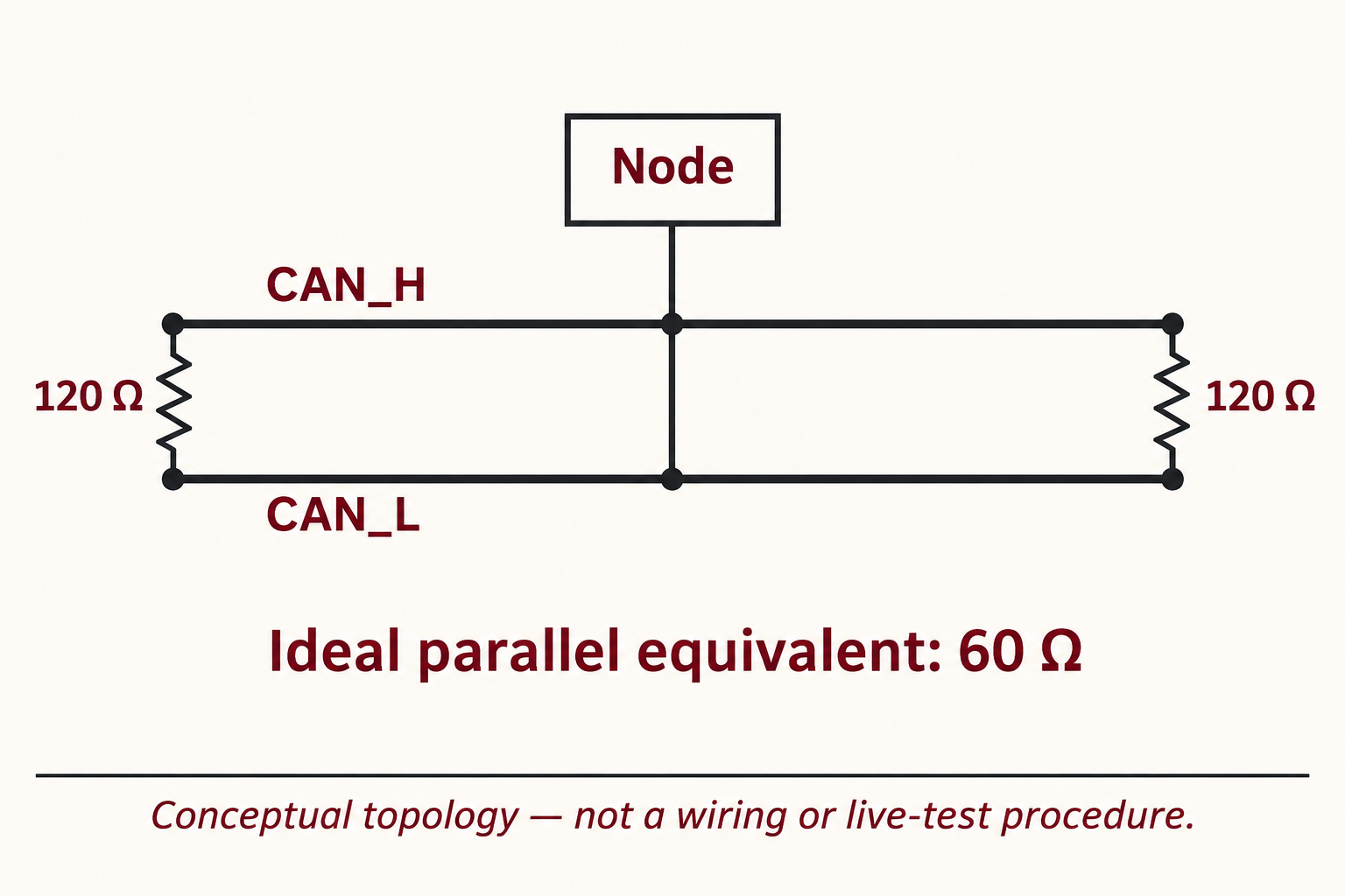
In the conventional high-speed CAN arrangement discussed in TI’s physical-layer application report, termination matches the intended line characteristic impedance at the physical bus ends. A common arrangement uses one 120 Ω resistor across the two signal conductors at each end. It does not place a 120 Ω termination at every connected node.
The distinction is physical topology. A network can contain intermediate nodes while retaining two physical ends. Counting devices does not tell you how many terminations the intended topology requires. The diagram below illustrates the conventional arrangement, not a connector assignment or a modification procedure for a particular vehicle or machine.
TI’s cited SLLA270 report dates from 2008. It is used here for this bounded physical-layer explanation, not as a claim of compliance with every current CAN variant or product requirement. The actual transceiver, network design and equipment documentation determine the applicable arrangement. A resistor value seen in one network is not a universal rule for all CAN interfaces.
What two 120 ohm resistors in parallel actually mean
Two ideal 120 Ω resistors connected across the same pair of ideal conductors are in parallel, even when they are drawn at opposite ends of the bus. Their equivalent resistance is 1/R = 1/120 + 1/120 = 1/60, so R = 60 Ω. This is a circuit-model calculation, not a statement that every complete network must present that value under every condition.
The equivalent value does not make resistor location irrelevant. The two physical end terminations serve a transmission-line purpose. Replacing them with a single 60 Ω component somewhere convenient changes the arrangement. Matching a simple equivalent resistance does not reproduce the distributed line’s termination at its two ends.
The calculation also does not provide a diagnostic verdict for connected equipment. Internal networks, switchable termination and other circuit paths can affect the result of an actual assessment. Electrical diagnosis needs the equipment’s defined procedure and conditions. This article does not prescribe probing or changing a powered network.
TI also describes split termination. In that arrangement, two nominal 60 Ω sections form a series termination at one end, with a midpoint network. That is a different use of the number 60 from the parallel equivalent of two 120 Ω end resistors across a whole ideal bus. Keep the topology with the arithmetic when comparing diagrams.
Specify the component and preserve its identity during handling
A useful component record includes the complete manufacturer part number, nominal resistance, tolerance, applicable power and voltage ratings, temperature conditions, package, assembly requirements and intended circuit role. For a termination application, retain the approved schematic reference as well. The phrase 120 ohm resistor should start the search, not finish the specification.
Keep the supplier label, lot identification and packaging information with the parts. Mixing visually similar parts with different tolerances or packages can turn a straightforward value check into an identity problem. For assemblies containing sensitive devices, handling controls belong to the assembly and packaging requirements; do not infer identical ESD sensitivity for every loose resistor.
CH-ESD’s ESD boxes and component storage containers can be considered for the documented storage route. Select compartments, support and labeling around the actual contents and access needs. A container does not verify the component value, approve a substitution or establish electrical compatibility.
Frequently asked questions
Can two resistors with the same nominal value be substituted? Only after checking the remaining specifications and the application. A matching value does not guarantee matching pulse capability, thermal limits, tolerance, package or assembly behavior. Use the approved part requirements rather than a value-only comparison.
Does a color band or printed code state the wattage? The examples here encode resistance and, where specified, tolerance. They do not provide a universal power rating. Identify the actual part and its data sheet before making a power decision; body size alone is not a complete rating specification.
References
- Vishay: resistor color-code chart — digit, multiplier and tolerance-band conventions.
- ROHM: nominal resistance values and markings — decimal marking conventions and nominal-value interpretation.
- Texas Instruments: SLLA270 physical-layer report — historical conventional high-speed CAN termination explanation, January 2008.
- Vishay: resistor FAQ — rating conditions and thermal considerations.
- EOS/ESD Association: control procedures and materials — handling controls for sensitive devices and assemblies.