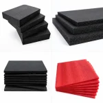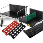


ESD foam inserts are useful when a component needs a defined pocket, repeatable orientation, and a packaging route that can be reviewed before production. The insert should be designed from the component envelope and handling sequence, then matched to the foam’s electrical role and finished fabrication. A black foam appearance alone does not establish a material class or a finished-package result.
For a supplier-ready request, describe the part, contact surfaces, access direction, movement between stations, cushioning need, and evidence required for the final configuration. The relevant ESD foam material options can then be evaluated as a family of possible constructions rather than as a promise that every grade behaves the same way.
1. Start with ESD foam inserts at the component envelope
The first design question is where the component must sit and how an operator will remove it. Record the largest envelope, fragile projections, connector clearance, contact surfaces, orientation, and whether the part arrives loose, bagged, or already nested. A pocket that looks close to the part may still create a problem if the operator has no finger access or if a cable, pin, or exposed surface becomes the removal point.
Separate the holding function from the cushioning function. The insert may need a shaped pocket, a flat support, a removable top layer, or a combination that keeps the item from shifting during movement. Keep the pocket geometry tied to the actual part family; do not convert a single sample into a universal drawing for every variant.
| Decision | Record before quoting |
|---|---|
| Pocket fit | Part envelope, orientation, clearance, and removal grip |
| Support | Fragile zones, contact surfaces, and movement route |
| Repeatability | Variant list, nesting direction, and inspection points |
2. Match the foam electrical role to the packaging route
Conductive, static-dissipative, antistatic, and shielding descriptions answer different questions. The required electrical role depends on the component, the contact path, the surrounding packaging, and the ESD control process. Treat the wording on a product family page as a starting point for a technical discussion. The grade, surface, layer construction, and finished insert should be confirmed for the real application.
Mechanical structure is a second axis. EVA, IXPE, PU, and EPE are material families that can be considered for different support and fabrication needs; the choice cannot be made from the family name alone. Ask which construction is available for the required cut, pocket depth, handling route, and contact condition, and request the supplier’s applicable test basis or material documentation for the finished part.
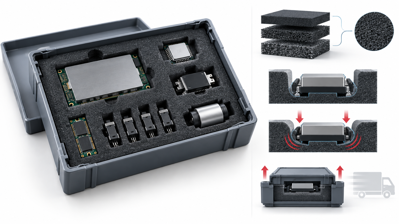
3. Design for access, replenishment, and transit
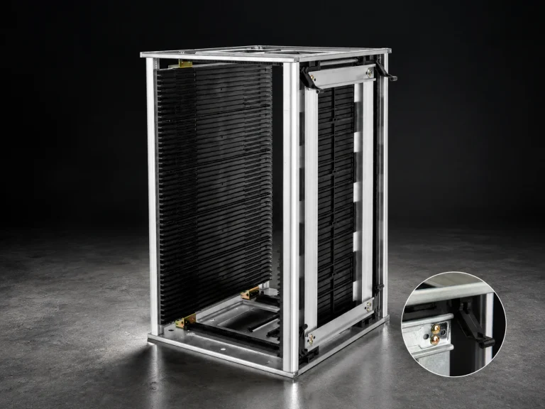
A packaging insert is part of a workflow. Check whether the operator loads from the top, front, or side, whether a lid or outer tote changes access, and whether the same pocket is used at receiving, assembly, inspection, and shipping. If the insert is moved inside an tray system, confirm how the insert is supported, lifted, cleaned, and returned to the line.
Plan for identification without placing labels where they can touch the component. Define the part number or lot separation outside the pocket, include an inspection view for missing or reversed parts, and state whether operators need one-hand retrieval. Transit design should also address shifting, stacking, and the handoff between internal movement and shipment; these are route decisions, not properties that can be inferred from foam color.
4. Send a supplier-ready foam insert brief
A useful request gives the supplier enough information to propose a configuration and enough boundaries to avoid unsupported assumptions. Include the following items:
- Part information: component family, largest envelope, fragile features, contact restrictions, and variant count.
- Use route: workstation, cart, rack, receiving area, or shipment; include loading direction and expected handling.
- Insert construction: foam family to review, pocket or support concept, outer carrier, lid or separator requirement, and fabrication preference.
- Evidence: material classification, applicable test method or test basis, drawing revision, sample inspection, and conditions attached to the result.
- Commercial fields: quantity by configuration, packaging for shipment, identification marks, and requested revision date.
This structure keeps the discussion about a finished insert and its route. It also leaves room for the supplier to recommend a material or fabrication method after the actual component and evidence requirements are known.
Before approval, run a sample review with the real component or a representative envelope. Check loading direction, removal force in practical use, unsupported edges, contact restrictions, identification, and the condition of the insert after the intended movement route. Record the revision of the drawing and the conditions used for the review so a later foam change can be compared with the approved configuration.