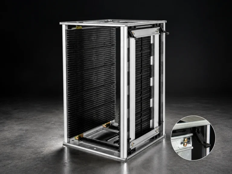


ESD storage shelves should be planned as a complete storage position: rack, carrier or container, grounding path, labels, and operator route. Choose the frame around the actual load and access pattern, then verify the installed configuration. A rack description alone does not prove that every shelf, accessory, and connection is suitable for the intended ESD-control process.
1. How to plan esd storage shelves around the stored carrier
List what each level will hold, the largest tray or container, approximate loaded weight, replenishment method, and the normal pick face. A rack for PCB magazines has different support and pitch needs from a shelf for closed totes. Check the highest normal pick, lowest container, and full-bay condition before freezing the layout.
Reserve space for labels, hands, and removal motion. Record floor, wall, aisle, and adjacent-equipment constraints because a shelf that fits on a drawing can become unusable when a loaded carrier must be turned or passed through the real route.

2. Verify the grounding and material path
Ask how the rack, shelves, accessories, and stored carriers participate in the site ESD-control program. Confirm material descriptions, connection points, bonding or grounding instructions, resistance evidence, test point, and the conditions attached to the result.
Do not infer that a metal frame automatically creates a complete grounding path, or that an ESD label applies to an accessory added later. Keep exact resistance, load, and certification statements conditional until the supplier provides configuration-level documentation for the rack that will be installed.
3. Use separation and visibility as operating controls
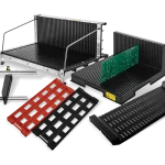
Use shelf positions to separate product families, lots, and process stages. Keep the label face consistent and reserve a clear replenishment route. If racks hold trays or magazines, check support surface, insertion depth, slot pitch, and the force required to remove a loaded carrier.
If bins share the same frame, match the opening to the operator’s reach and prevent dividers, covers, or rear stops from blocking the intended pick face. Validate the layout with a representative carrier and normal load, then keep the approved accessory combination with the bay record.
4. Prepare a supplier and installation checklist
Send bay dimensions, level count, load by level, carrier or container type, access side, floor or wall condition, label method, quantity, and route. Request a drawing, material and coating description, accessory compatibility, load information, grounding or bonding instructions, and the proposed verification method.
Use the CH-ESD ESD Rack family route to review available formats. For a carrier-based layout, compare the matching ESD rack product page with the real carrier dimensions, then approve the exact configuration after a physical fit and site check.
Before approving an ESD rack, build one representative bay and load it with the heaviest normal carriers. Insert and remove items from every level, check label visibility, and verify that the intended connection points remain accessible. Record the shelf position, accessories, carrier type, load condition, and test method used during acceptance. This creates a repeatable baseline for later bays.
The grounding route should remain inspectable after the rack is full. Avoid placing cartons, bins, or floor protection over connection points or test locations. If conductive containers or PCB magazines are part of the route, confirm how they contact the support surface and whether liners, paint, dust, or replacement accessories could interrupt the intended path. Document these conditions rather than relying on the frame material alone.
For expansion, duplicate only the approved drawing and accessory set. Recheck the floor, location, load, and operator reach at each new bay. If ESD racks move between receiving, inspection, and production, treat each location as a new installation condition. A consistent bay record makes changes visible and helps maintenance teams replace shelves or connections without losing the approved layout.
Include maintenance in the approval record. Define how shelves are cleaned, how fasteners and connections are inspected, and which replacement parts may be used. Recheck the bay after relocation, impact, accessory changes, or a significant load change. This keeps ESD storage shelves aligned with the verified installation rather than with an old catalog description.
References
- EOS/ESD Association: ESD Fundamentals, Part 3 — ESD control procedures and material categories.
- EOS/ESD Association: ANSI/ESD S541-2026 — Packaging properties and test-method reference for electrostatic-sensitive items.
- IEC 61340-5-1:2024 — ESD control-program requirements and implementation context.
- Current SERP product reference — A current US search result used as topic context, not as a CH-ESD specification.
- Additional current SERP reference — A current US search result used as topic context, not as a CH-ESD specification.