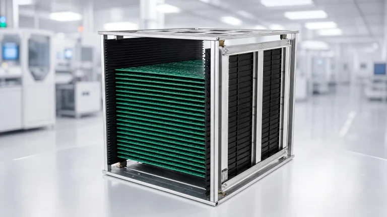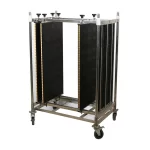


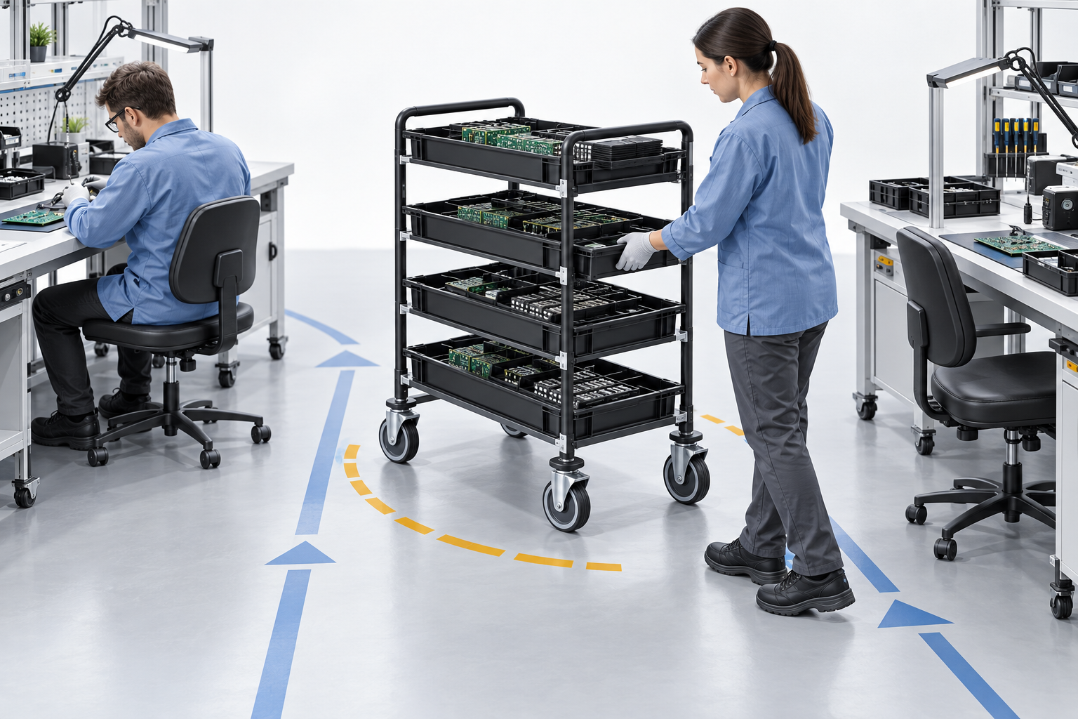
An ESD tray cart carries trays of electronic components between workstations. It differs from a PCB slot cart: the tray needs shelf or rail support, while a slot cart holds boards by their edges. Select a tray cart by loaded tray size, support spacing, retained position, access height, and the real movement route.
| Load | Suitable support to specify | Do not assume |
|---|---|---|
| Loaded component tray | Shelf or rails supporting the tray footprint | PCB edge slots will hold a tray |
| Bare PCB | Verified board grooves or slots | A shelf alone locates and protects the board |
| PCB magazine | Support for the complete magazine | Magazine outer dimensions equal board dimensions |
Check outside fit and component clearance separately
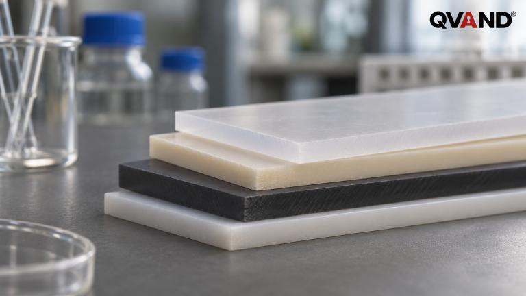
The published QD-9805112 grid tray is 457 × 312 × 39 mm outside, while its listed inside size is 417 × 292 × 30 mm. Use the outside footprint to check a proposed shelf or rails. Use the inside space and assembled compartment drawing to check the component.
A shelf opening that fits the empty tray is only the first check. Add cover height, protruding components, fingers or lifting tools, and the underside of the next support level. Then check that the tray cannot slide off its support during a normal turn. These clearances need the proposed cart drawing; they cannot be calculated from the tray’s nominal size alone.
CH-ESD’s width-adjustable PCB cart publishes board grooves. Those grooves do not establish that the cart accepts this grid tray. Compare the trolley formats and ask specifically for tray support.
1. How to plan an esd tray cart around the work route
Record the tray outside dimensions, usable opening, loaded weight, quantity per trip, and whether trays are stacked, separated, or supported in slots. Map the full route from receiving or storage to the workstation, including thresholds, turns, lifts, narrow aisles, and the point where the operator removes a tray.
A cart that fits an empty tray may behave differently at full load. Test the representative tray, the highest normal stack, and the normal replenishment motion. Keep the route part of the specification so a supplier can recommend wheel arrangement, handle position, shelf pitch, and braking requirements for the actual floor and workflow.
2. Verify access and stability at the working height
Choose the access direction around the operator’s reach and the workstation interface. Front access may suit line-side picking, while a deeper shelf can increase reach and obstruct labels. Check that a loaded tray can be removed without striking an adjacent level or changing the balance of the cart.
Request the cart material description, shelf or slot support, wheel and brake information, load basis, and any grounding or bonding instructions. Do not infer a complete ESD path from a metal frame or wheel. The supplier should state which parts are included in the tested configuration and how the result is verified.
3. Control identification and handoff between stations
Use consistent tray and cart identification so the next station can confirm SKU, lot, status, and quantity without moving the load. Separate released, waiting, rejected, and in-process trays by a visible rule. If the same cart serves several stages, define where a tray may be parked and who owns the handoff.
Check the cart when turning, stopping, and passing through the route. Wheels, handles, shelf lips, and tray stops should support the normal movement pattern. Record the representative load and route used during acceptance so a future cart or replacement shelf is compared against the same conditions.
4. Build a supplier-ready tray cart request
Send tray dimensions, loaded weight, levels or slots, quantity per trip, access side, floor condition, route constraints, brake preference, identification method, and required ESD evidence. Ask for a drawing, material and finish description, included accessories, load information, grounding or bonding instructions, and the proposed verification method.
Compare the general ESD cart selection guide for wheels, brakes, floor conditions, and grounding checks. CH-ESD’s mobile ESD magazine rack publishes PCB grooves and slots. The product is a board-handling candidate, so ask for a tray-support drawing before using it to carry loaded trays.
Run a route trial before approving the cart. Load representative ESD trays, move through the narrowest aisle and tightest turn, stop at the workstation, and remove the highest and lowest trays. Check that brakes hold on the actual floor, handles remain reachable, and trays do not shift during normal acceleration or stopping. Record the load and route used in the test so acceptance can be repeated.
The ESD pcb tray and the cart should also be reviewed as one handling system. A tray lip, divider, cover, or label can change the clearance even when the nominal tray footprint is unchanged. Ask for the usable shelf or slot dimensions and compare them with the loaded tray, including any part that protrudes above the rim. Confirm the cleaning method for wheels, shelves, and contact areas.
For receiving inspection, verify the drawing, wheel and brake arrangement, shelf or slot count, accessories, and identification points against the approved configuration. Keep replacement wheels and accessories under the same review rule. A change in wheel material, shelf insert, or tray stop can affect movement and ESD-control assumptions, so the approved parts list should remain with the cart record.
References
- EOS/ESD Association: ESD Fundamentals, Part 3 — ESD control procedures and material categories.
- EOS/ESD Association: ANSI/ESD S541-2026 — Packaging properties and test-method reference for electrostatic-sensitive items.
- IEC 61340-5-1:2024 — ESD control-program requirements and implementation context.