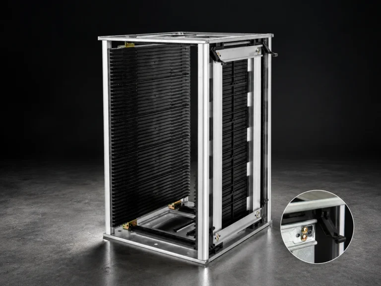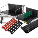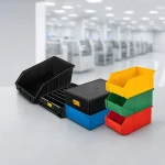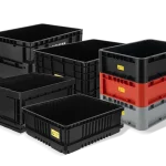


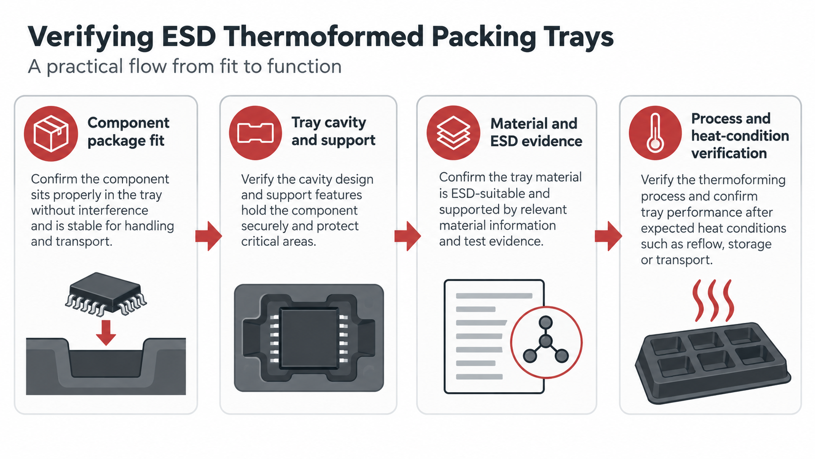
The phrase “packing tray ESD thermoformed” combines a product, an ESD requirement, and a manufacturing process; approve the offered tray from evidence, not from the process word alone. Confirm the cavity and support points first, then verify the material, ESD properties, heat or process exposure, handling route, and documentation for the exact tray.
The CH-ESD ESD Tray family includes several tray types. The category page is a route to the product family; it does not make every geometry, material, or manufacturing process interchangeable.
1. Define what a packing tray ESD thermoformed request must support
Record the part or package outline, cavity count, orientation, support areas, loading method, and the clearance needed for removal. A PCB or semiconductor package should not be allowed to rock, touch adjacent cavities, or rely on a feature that is not shown in the approved drawing.
For a grid tray, the grid can separate components and support sorting, but the published product page still needs to be read at model level. It lists multiple QD models, several outer and inner dimensions, detachable-grid notes, optional covers, and temperature-resistance customization options. Those entries describe the named page and models; they are not a universal tray standard.
| Approval area | Buyer evidence |
|---|---|
| Cavity fit | Part outline, cavity drawing, support points, clearance, and orientation. |
| Process | Material/process description and revision-controlled drawing. |
| ESD and heat | Material classification, test basis, temperature conditions, and applicable packaging evidence. |
Approve the fit with representative components whenever possible. Check insertion and removal at the normal workstation, observe whether the part contacts a sensitive surface, and confirm that the tray remains stable when partially loaded. The approval sample, cavity drawing, and revision should identify the same configuration so later production lots can be compared with the accepted basis. Record the accepted loading orientation and removal method in that approval record.
If trays will be stacked, moved on a cart, or placed in a rack, include those interfaces in the fit review. Cavity clearance alone does not show whether a cover, upper tray, label, or handling tool will interfere with the part.
2. Treat “thermoformed” as a process requirement to verify
The query specifies thermoforming, but the available CH-ESD category and product pages list tray types and model information rather than a single process statement for every tray. Put the process requirement in the RFQ: ask whether the offered tray is thermoformed, what material and thickness apply, how the cavity is formed, and which drawing revision controls production.
This distinction prevents a common error: treating a visible plastic tray as proof of a particular process or performance. A photograph can show a cavity layout. It cannot prove the manufacturing route, material formulation, heat history, or ESD test result.
3. Check ESD requirements against the handling route
EOS/ESD guidance describes packaging and material-handling containers inside an EPA as low charging and dissipative or conductive. Outside the EPA, packaging also needs a structure that provides discharge shielding. Define whether the tray remains in a controlled area, moves between stations, enters storage, or leaves the facility before choosing the evidence you need.
Ask for the material classification, test method or test basis, measurement conditions, and scope of the result. The ESD property is part of a control system that also includes handling and grounding conditions; a tray alone cannot replace that system.
Also define the process temperature, duration, cleaning method, and reuse cycle that the tray will encounter. A published temperature option should remain tied to the named product and conditions. It does not establish performance for every tray, every exposure time, or every cleaning chemistry.
4. Separate IC tray requirements from general packing trays
The CH-ESD IC Tray page describes semiconductor packaging and testing use and lists package families such as BGA and QFN. It also publishes model-specific matrix, temperature, and surface-resistance information. If the tray is for an IC package, identify the package family and the current device or carrier requirement before selecting a general PCB packing tray.
If a product page or RFQ uses the phrase “JEDEC tray,” name the exact package, matrix, drawing, and document requirement that the offered configuration must meet. The phrase alone is not enough to approve a cavity or prove compatibility with a specific device.
5. Build a supplier-ready tray request
- Part definition: package or board type, envelope, orientation, quantity, and sensitive surfaces.
- Cavity drawing: cavity dimensions, support points, draft or release needs, pitch, and allowable movement.
- Process: thermoformed requirement, material, thickness, drawing revision, tooling, and change control.
- ESD evidence: material category, test method, test conditions, and whether the result applies to the offered configuration.
- Use route: EPA location, handling equipment, storage time, temperature exposure, cleaning, and shipment conditions.
Review the ESD Tray family after the requirements are clear
Start with the ESD Tray category, then open the grid tray or IC Tray page that matches the use case. Use the page to identify a candidate family, then request the configuration drawing and evidence before approving the tray.
References
- EOS/ESD Association: ESD Fundamentals, Part 3 — packaging and material-handling container context inside and outside an EPA.
- EOS/ESD Association: ANSI/ESD S541-2026 — packaging properties and evaluation context for ESDS items.
- IEC 61340-5-1:2024 — ESD control-program scope for organizations that handle electronic parts and equipment.