

Circuit opening means interrupting a path through which current is intended to flow. An open switch can do this deliberately; a broken PCB connection can do it unintentionally. The term describes the connection state, not a complete diagnosis of why a board stopped working.
For a PCB investigation, separate three questions: what path should exist, what was actually observed, and what evidence supports the proposed cause. A missing function, a visible gap and a meter indication are different observations. This guide explains their relationship and provides a useful handoff record without giving energized troubleshooting or repair instructions.
What an open circuit means
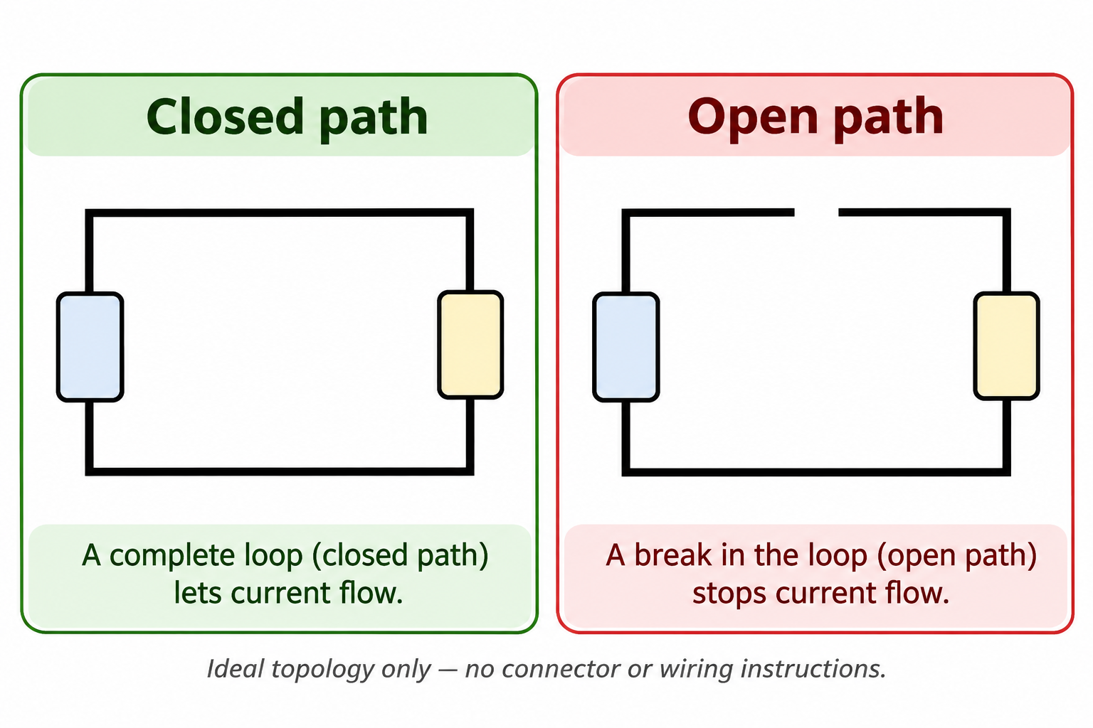
A complete circuit provides the relevant current path. An open circuit interrupts that path. In an ideal simple series model, introducing a gap stops steady current around that loop. The physical location could be a switch, a connector interface, a conductive track or another connection, but the word “open” does not identify which one.
The intended design is the reference. A disconnected option on one board revision may be intentional while the same-looking condition on another revision may be a fault. Before describing a PCB opening, identify the correct schematic and assembly configuration. Otherwise, an investigation can begin by treating an unpopulated option as a manufacturing failure.
| Description | What it establishes | What it leaves unresolved |
|---|---|---|
| Intended open switch | A design-controlled path is interrupted | Whether the rest of the circuit is functioning correctly |
| Visible track interruption | A physical gap appears at a specific location | Its full electrical consequence and origin |
| Suspected open connection | Available evidence suggests a missing path | Whether the observation proves that diagnosis |
| Equipment does not operate | A function is absent under stated conditions | Whether an open circuit is responsible |
Use the narrowest description supported by the evidence. “Suspected interruption between identified nodes” is often more informative than “bad board.” It tells the next person where to look in the design record while preserving uncertainty about the cause. Fluke’s continuity explanation supports the distinction between a complete path and an interrupted one.
Intentional switching versus an unwanted open
Opening a circuit can be the desired operating state. A switch may intentionally interrupt a branch, and an assembly option may intentionally leave a connection absent. An unwanted open is different because the approved configuration requires a connection that is not present. The same physical absence can therefore have a different meaning in different designs.
This distinction is useful when communicating across design, assembly and purchasing teams. The person reporting a concern may only see the assembled board. The designer may know that a connector or link belongs to an optional configuration. A record that includes the revision and assembled option prevents those two views from being mistaken for contradictory test results.
Consider an illustrative build with two approved assembly options. One includes a link and the other intentionally omits it. A photo showing the vacant location cannot establish a defect until the board’s required option is known. This example concerns document control; it makes no claim about a particular component or manufacturing process.
State the expected condition before the suspected failure mechanism. A useful report says which drawing requires the connection, which assembly revision was received and what observation raised the concern. That sequence gives a supplier an actionable question without assuming that an intentional design feature is damage or that a visible difference caused the reported functional problem.
Open circuits and short circuits are different
An unwanted open removes an intended conductive path. A short introduces an unintended low-resistance connection between nodes that should not be connected that way. These are different circuit conditions, even though either may prevent normal operation. A generic report of “no output” does not distinguish between them.
| Condition | Relationship to the intended design | Evidence worth identifying |
|---|---|---|
| Open path | Required connection is absent or interrupted | Exact nodes, location and expected connection |
| Unintended short | An unwanted low-resistance connection exists | Which separate nodes appear connected |
| High-resistance connection | A path exists but its behavior may not meet requirements | Defined result, conditions and acceptance basis |
| Intermittent symptom | Behavior changes across observations | Timing and conditions, without prematurely assigning a cause |
Do not use “open” as a synonym for every unreliable connection. A high-resistance path and a fully interrupted ideal path are different models. An intermittent symptom also needs its own record because a single observation may not represent the condition at another time. The investigation should retain that distinction until the available evidence supports a stronger conclusion.
For production communication, separate the failure description from the suspected mechanism in different fields. This allows a later investigation to confirm or revise the mechanism without erasing the original observation. It also makes repeated concerns easier to compare because similar symptoms do not have to be forced into the same unsupported root-cause category.
Zero current does not mean zero voltage
Take a hypothetical ideal series circuit with a 5 V source and a 1 kΩ load. With the path closed, the simple calculation gives 5 ÷ 1,000 = 0.005 A, or 5 mA. With an ideal gap in that series loop, steady current is zero. These teaching values describe a model, not an instruction to construct or probe a circuit.
The open condition does not establish zero voltage across the gap. Current around a path and potential difference between two points are different quantities. Concluding that a circuit is safe to touch because a load draws no current would confuse those quantities. The model’s zero-current statement is not a safety verification.
For a separate hypothetical leakage model, replace the ideal gap with an assumed 1 MΩ leakage path in series with the same 1 kΩ load and 5 V ideal source. The calculated steady current is 5 ÷ 1,001,000 A, approximately 5 µA, rather than the ideal open circuit’s zero. This invented resistance represents a finite path in the model; it is not measured PCB leakage, an acceptance limit or a proposed test. The comparison shows why an ideal open and a very high but finite resistance are different descriptions.
Real circuits can also include other paths, components and transient behavior. An ideal open in one branch does not imply that every branch in a parallel arrangement has stopped carrying current. The scope of the conclusion must match the path represented. A board-wide statement needs board-wide evidence rather than a conclusion copied from one simple series example.
When documenting an observation, preserve the operating condition and the specific function involved. “This indicator did not illuminate in the stated configuration” is an observation. “The whole board has no electrical energy” is a much broader claim that the observation does not support. Keeping those statements separate improves both technical communication and the quality of subsequent investigation.
Why a meter indication is not a complete verdict
A continuity indication depends on the instrument, selected mode, measurement arrangement and the criterion used by that instrument. Fluke explains that continuity relates to a complete path and that audible indications use instrument-specific criteria. There is no universal beep threshold that can be copied into every PCB acceptance rule.
Similarly, an overrange display or a missing beep records an instrument response under particular conditions. It should not be translated automatically into “component destroyed” or “PCB trace broken.” The intended circuit, connected components and the selected assessment method still need to be understood. This article does not provide live probing steps; continuity assessment belongs only where voltage is absent and the applicable controlled procedure permits it.
A report is more useful when it preserves the original indication alongside the interpretation. Identify the instrument and mode from the authorized test record, the relevant test points or nodes, and the expected result defined by the approved procedure. If that context is unavailable, record the limitation instead of inventing a pass or fail threshold.
The difference is practical: a supplier can investigate a documented result, but cannot reconstruct an unspecified “meter says open” statement reliably. A photo of a display may help retain the observation, yet it does not show the entire measurement context. Keep the procedure reference and board identity with the image rather than expecting the image to carry the diagnosis.
Separate manufacturing, assembly and handling evidence
A suspected PCB path interruption can prompt questions about fabrication, assembly or later handling. Those are investigation categories, not causes established by the word “open.” A visible mark, the location of a concern and the point at which it was first observed can help frame the investigation without proving a mechanism.
Build a timeline from recorded events. Identify the board or lot, the last documented acceptable result, the first relevant observation and any known movement or processing between them. If a stage was not checked, mark it unknown. An unobserved stage cannot honestly be described as the point where a defect originated.
Keep physical and electrical evidence distinct. A damaged-looking edge may be relevant to support and handling, while an electrical result concerns the evaluated connection. They can support the same investigation without establishing the same fact. Avoid claiming that one photograph proves an internal connection failure unless the investigation actually supports that conclusion.
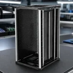
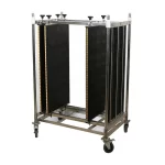
For the handling portion, compare the full board envelope and permitted support regions with the carrier arrangement. ESD magazine racks for PCB handling are a relevant option when boards need separation and an appropriate support route. Carrier selection does not repair an open circuit, verify electrical function or automatically establish the origin of damage.
Prepare a useful PCB investigation record
The handoff should allow another person to identify the exact assembly, understand the expected path and distinguish observation from interpretation. It does not need a confident root-cause statement before the evidence exists. The following worksheet keeps the information most likely to be lost in an informal message together.
| Record field | Useful entry | Avoid substituting |
|---|---|---|
| Identity | Board identifier, revision, lot and assembled option | A generic product family name |
| Expected condition | Drawing or approved requirement for the connection | An assumption based on a similar-looking board |
| Observation | Location, symptom, original result and conditions | A diagnosis presented as the observation |
| Supporting record | Dated photos and relevant authorized test reference | An unexplained display image |
| Timeline | Last known result and first observation | An invented point of origin |
| Handling context | Carrier, support locations and relevant movement records | A claim that any rack guarantees protection |
| Open question | The specific evidence or assessment being requested | A demand to confirm a predetermined cause |
For example, describe a suspected interruption at a named connection on a stated revision, identify the observation that raised it and request confirmation against the approved connectivity. Keep any suspected handling contribution in a separate field. This makes it possible to investigate both the electrical requirement and the physical history without forcing one explanation too early.
After an investigation, retain the original report and add the confirmed disposition. Replacing the first observation with the final diagnosis can obscure why the issue was escalated and what evidence changed the conclusion. A clear record supports future comparisons while keeping unconfirmed events from becoming accepted manufacturing history.
Questions about circuit opening
Can a board work even if one circuit branch is open?
It can, depending on the design and which function that branch serves. A branch-specific interruption does not automatically describe every other path. The useful question is which required function and connection are affected. Compare the observation with the correct schematic and assembly configuration rather than applying a board-wide verdict from one branch.
Does finding an open connection prove ESD damage?
No. An interrupted path is an electrical or physical condition; ESD is a proposed damage mechanism that needs appropriate supporting evidence. Electrostatic controls and suitable carriers remain relevant to handling, but neither the presence nor absence of one control identifies the cause of an observed opening. Preserve the evidence and let the investigation establish the mechanism.