

A battery eliminator circuit (BEC) is a voltage-regulation function that powers receiver electronics, servos or another lower-voltage subsystem from a main battery. It removes the need for a separate battery for that subsystem. It does not remove the main battery, replace the motor controller or make every connected device compatible with the same voltage.
The useful buying question is not simply whether a controller includes a BEC. It is whether the complete receiver-power path supports the required voltage, sustained current and short load changes under its actual operating conditions. Those checks also explain why a large motor-current number on an electronic speed controller can tell you very little about receiver-power capacity.
What a battery eliminator circuit powers
In radio-controlled equipment, the propulsion system and the control electronics have different power requirements. The motor controller handles the motor-power function. A BEC provides a regulated supply for the compatible control electronics. The two functions may share one housing or appear as separate modules, but their ratings remain separate.
HOBBYWING describes its external UBEC as a switching DC/DC regulator for receivers and other electronic devices. That is a useful functional definition: battery-side input becomes a regulated electronics supply. The receiving equipment still determines which output voltage and supply arrangement are acceptable. The word BEC alone does not identify a connector, pin assignment or operating range.
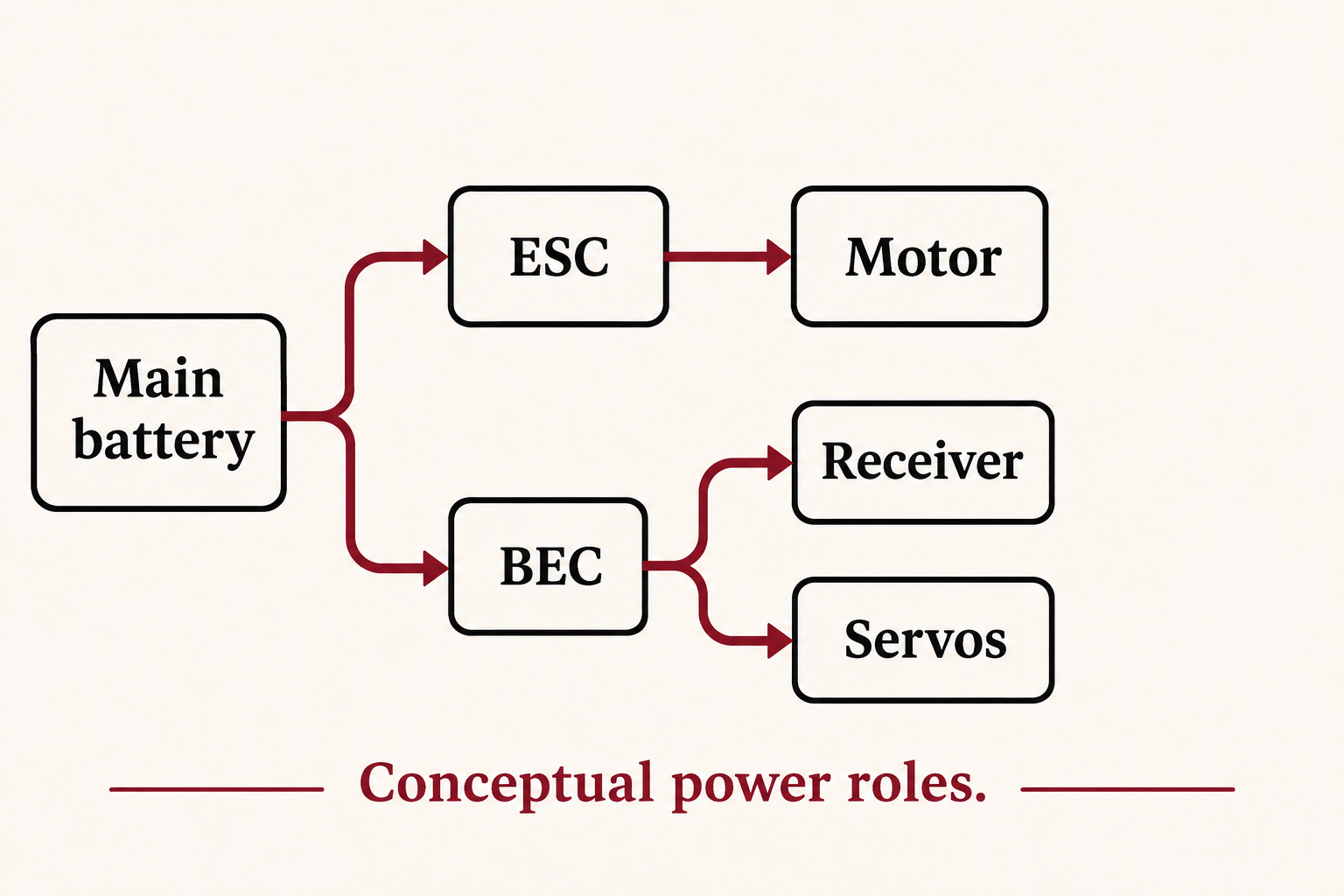
For a system review, write down the two paths separately: motor power and receiver/accessory power. Put each specification beside the path it describes. This simple separation prevents a procurement error in which an impressive motor rating is copied into the receiver-power requirement. It also makes later questions to the equipment manufacturer much more precise.
BEC, ESC, UBEC and SBEC: separate the function from the label
| Term | Useful interpretation | What the label does not establish |
|---|---|---|
| BEC | Regulated power for a compatible subsystem | Its permitted input, output, current or protection features |
| ESC | Electronic speed controller; motor-control function | The capacity of any receiver-power output |
| External BEC / UBEC | A separate regulator module in the intended system | One universal regulator topology or installation method |
| Switching BEC / SBEC | A regulator using a switching conversion approach | Efficiency, noise or thermal performance in your installation |
Product names are not a substitute for the specification table. Manufacturers use different naming conventions, and an abbreviation on a retailer listing may omit important limits. Read the manufacturer’s description for the exact model and revision. In particular, distinguish the ESC’s motor rating from the BEC’s own output specification, even when both numbers appear on the same page.
An external BEC is worth evaluating when the intended system needs a separate receiver-power function or when the existing one does not satisfy the documented requirement. Adding a second source is not automatically an upgrade. Some systems need a defined isolation or power-selection arrangement; an improvised parallel connection can create a different electrical problem. Follow the relevant equipment manuals rather than a generic wire-color rule.
Match the output voltage before comparing current
The output setting must be compatible with every device on that supply path. A receiver, servo, lighting module and accessory may not have identical operating limits. A voltage that suits one item can be inappropriate for another. List the complete set of loads before choosing a setting, rather than treating the receiver’s rating as permission for everything downstream.
Record the allowed supply range from each device’s documentation and compare the ranges. If there is no shared allowed setting, the specification needs a different power architecture or different equipment. A larger current rating does not solve that mismatch. Likewise, the regulator’s input limit must cover the intended battery condition, not merely a convenient nominal number from a label.
A practical voltage record has four columns: exact load model, allowed supply range, chosen rail and document revision. Keep adjustable-output settings with that record. This turns a vague request for a stronger BEC into a checkable requirement. It also lets a replacement receiver or servo trigger a focused compatibility review instead of silently inheriting the previous setting.
Build a current budget around simultaneous demand
Current capacity needs both a sustained-load view and a transient-load view. Peak current describes a different condition from continuous current; the duration, repetition and thermal assumptions matter. Castle’s regulator information and support guidance make clear that receiver-power selection depends on the actual equipment and operating conditions. A single large number cannot replace those conditions.
Consider an arithmetic example only: four loads each drawing 0.25 A during one operating condition, plus a 0.15 A receiver load, total 1.15 A. If the four loads each reach 1.2 A together, the corresponding total becomes 4.95 A. These are invented teaching inputs, not measured servo specifications or a recommendation to buy a regulator carrying a particular amp label.
| Budget item | Illustrative calculation | Question the calculation leaves open |
|---|---|---|
| Example steady condition | 4 × 0.25 A + 0.15 A = 1.15 A | Does that condition represent the real sustained duty? |
| Example simultaneous peak | 4 × 1.2 A + 0.15 A = 4.95 A | How long does the peak last and how often does it recur? |
| Actual selection | Use documented or measured load behavior | Can regulator, connectors and distribution support that behavior? |
The benefit of the worksheet is its explicit assumptions. A team can replace each teaching value with a documented load value or a suitable measurement, identify simultaneous demands and compare the resulting envelope with the regulator’s specification. There is no universal extra percentage that makes an unknown load safe. Preserve the assumptions alongside the result so another engineer can reproduce the decision.
Linear versus switching BEC: heat changes the comparison
A linear regulator and a switching converter manage the voltage difference in different ways. For a simplified linear-regulator estimate, ignoring quiescent-current effects, the dissipation is approximately (input voltage − output voltage) × load current. TI’s regulator guidance explains why conversion method and power dissipation belong in the supply decision alongside output accuracy and noise requirements.
For example, a hypothetical linear regulator converting 12 V to 6 V at 1 A would dissipate approximately 6 W under that simplified calculation. The example describes an energy balance, not an acceptable receiver supply or a thermally approved design. It does not show that a particular module can remove that heat. Its value is to make the thermal question visible before a buyer compares price and current labels.
A switching BEC can reduce conversion loss in suitable conditions, but switching operation does not establish one guaranteed efficiency or noise result. Input voltage, output voltage, load and layout all matter. Compare the manufacturer’s curves and stated conditions for the candidate module. Do not transfer the performance of one regulator or one laboratory condition to a different product simply because both are described as switching.
The enclosure and mounting environment belong in the review as well. A rating established with specified airflow cannot automatically be read as a sealed-compartment rating. Keep the intended installation conditions with the current requirement. If the necessary thermal information is missing, record that gap for the manufacturer instead of assuming a headline current number covers every mounting arrangement.
Read power symptoms without guessing a wiring repair
A receiver reset or a problem that appears when several accessories operate is a reason to investigate the supply path, not proof that the BEC is defective. The regulator, battery condition, distribution path, connector condition and equipment compatibility are separate questions. A useful fault report records what changed, which loads were active and the exact models and settings involved.
Avoid solving an uncertain symptom by raising the output voltage or adding another power source. Those changes can alter compatibility before the actual cause is understood. Keep powered diagnosis and model-specific connection changes within the equipment manufacturer’s procedures. For a procurement discussion, a clear symptom and configuration record is more useful than a guessed replacement part number.
A selection record that can survive a component change
Before committing a regulator to a repeat build, keep the main-battery specification, every powered load, allowed output setting, sustained and transient demand, thermal conditions and manufacturer documents together. Identify who approved the configuration and which revision was reviewed. A new servo, different receiver or revised operating condition should be compared with this record rather than treated as an equivalent item by appearance.
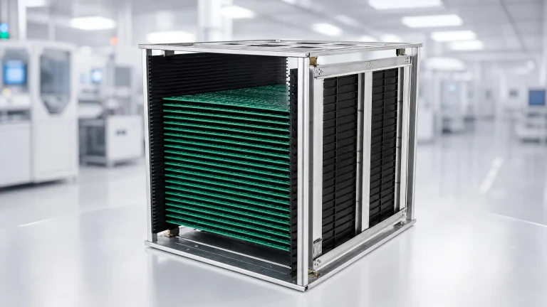
For electronics manufacturing and storage, this power-function review is separate from protecting unpowered boards. CH-ESD’s ESD component tray range is relevant at the handling stage: compare the board envelope, support points and removal access for the actual assembly. A tray does not establish power compatibility or prove that a finished regulator passed an electrical test.
A useful handoff therefore contains two distinct decisions. The electrical record identifies the qualified supply arrangement. The handling record identifies the board, carrier and protective packaging used between operations. Keeping them separate prevents an ESD label, a storage format or a large current figure from being mistaken for evidence about a different part of the system.
FAQ
Does a BEC charge the main battery?
A BEC’s receiver-power role is regulation for a compatible subsystem, not battery charging. A charging function requires its own specified equipment and charge-control method. Do not infer charging capability from the presence of a regulator or from a module’s input connector.
Can one BEC supply every accessory?
Only an explicitly compatible supply arrangement can support the selected loads. Compare every accessory’s allowed voltage and the combined load envelope with the regulator and distribution specifications. If the required information is missing, the shared supply is not yet a demonstrated match.
References
- HOBBYWING UBEC manual — manufacturer explanation of the regulated receiver-power role and model-specific conditions.
- Castle voltage regulators — external BEC product scope.
- Castle support FAQ — receiver-power compatibility and equipment-specific guidance.
- Texas Instruments regulator comparison — linear and switching conversion considerations.
- EOS/ESD Association fundamentals — handling and protective material context.