

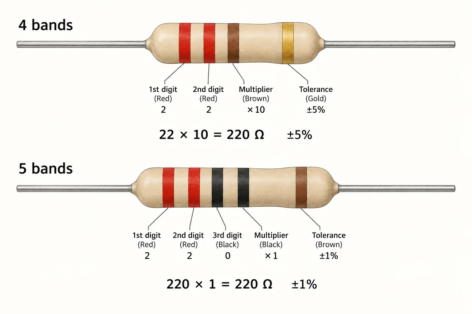
The 220 ohm resistor color code is red–red–brown for the value bands of a four-band resistor. A common fourth band is gold, meaning ±5% tolerance. On a five-band 220 Ω resistor, the value bands are red–red–black–black; a brown fifth band means ±1% tolerance. The nominal resistance is the same, but the positions have different jobs.
Count the bands before decoding them. Treating a five-band part like a four-band part moves the multiplier into the wrong position and produces the wrong answer.
220 ohm resistor color code with four bands
The first two bands supply the significant digits. Red represents 2, so two red bands give 22. The third band is a multiplier: brown means multiply by 10. Therefore, 22 × 10 = 220 Ω. The final gold band describes tolerance, not another digit.
| Position | Color | Meaning |
|---|---|---|
| 1 | Red | First digit: 2 |
| 2 | Red | Second digit: 2 |
| 3 | Brown | Multiplier: ×10 |
| 4 | Gold | Tolerance: ±5% |
A tolerance band may be spaced farther from the value bands. Use that spacing as a clue rather than a substitute for the manufacturer’s marking convention. Gold or silver at the end is useful for recognizing the tolerance position on many common four-band components.
Five bands: red, red, black, black, brown
A five-band marking uses three significant digits before the multiplier. Red, red and black give 220. The fourth band, black, means ×1. The final brown band means ±1% tolerance. Thus, 220 × 1 = 220 Ω.
The two neighboring black bands do not serve the same function: one is the third digit and the other is the multiplier. This is why remembering only a string of colors is less reliable than assigning each band its position.
What tolerance means for a 220 Ω part
Tolerance specifies permitted deviation from nominal resistance under the applicable specification conditions. For the two examples above, the arithmetic is:
- ±5%: 220 × 0.05 = 11 Ω, giving 209–231 Ω.
- ±1%: 220 × 0.01 = 2.2 Ω, giving 217.8–222.2 Ω.
These calculated intervals are not a complete acceptance procedure for an installed resistor. Temperature, instrument uncertainty and other connected paths can affect a reading. A measured value should be interpreted under the component specification and the applicable test method.
Resistance tolerance is also different from temperature coefficient. Vishay treats these as separate resistor characteristics: tolerance concerns the permitted nominal deviation, while temperature coefficient describes resistance change with temperature. Neither should be inferred from the component’s body color.
Avoid the 220 Ω versus 2.2 kΩ mistake
For a four-band part, red–red–brown gives 22 × 10 = 220 Ω. Red–red–red gives 22 × 100 = 2,200 Ω, or 2.2 kΩ. Changing just the multiplier changes the resistance by a factor of ten. Write the multiplier explicitly when a marking is difficult to read.
If paint is faded, discolored or ambiguous, retain the part’s uncertainty. A guess from a photograph is not a reliable substitute for a traceable part number. The bill of materials identifies the intended resistor at that board position. Use a package label to identify a loose resistor only when the part can be traced to that package.
What the bands do not tell you
A correct nominal value does not establish a suitable replacement. Power rating, maximum working voltage, construction, dimensions and application requirements still need to match. Two 220 Ω resistors can differ in these properties even if their value bands agree.
For a component record, capture nominal resistance, tolerance, manufacturer part number and package or physical size. Keep rating information with that record instead of expecting a color-code photograph to contain the whole specification.
During electronics assembly, identified components and boards may also need organized handling. Quan Dun’s ESD tray range is a handling option to assess against the actual assembly geometry. A tray does not verify resistor value or replace component traceability.