
A prototype circuit board is a physical platform used to answer a development question before the design is finalized. It may be a solderless breadboard, a solderable board with an existing connection pattern, or a fabricated PCB. The right choice depends on what the prototype must demonstrate, not simply which format is cheapest or quickest to assemble.
A circuit that works on one platform does not automatically prove the final layout, enclosure fit or manufacturing route. This guide compares the formats, separates the evidence each can provide and gives a practical revision and supplier-handoff record. The aim is to make the next prototype answer a defined question instead of repeating an unclear experiment.
Prototype circuit board: start with the question
Before choosing a board, write the decision the build should support. You may need to explore connectivity, evaluate behavior in a particular layout, confirm mechanical clearances or review a manufacturing handoff. Those tasks can overlap, but they do not require the same physical evidence.
| Prototype purpose | Useful evidence to plan | What remains separate |
|---|---|---|
| Explore a circuit concept | A documented configuration and observations under stated conditions | Final PCB layout and production qualification |
| Evaluate a proposed layout | The actual routed revision and relevant operating observations | Whether every future manufacturing condition is covered |
| Check mechanical fit | Board outline, mounting and complete component envelope | Electrical behavior and assembly process capability |
| Prepare manufacturing handoff | Controlled design outputs and defined assembly options | Proof that the delivered units meet every requirement |
For example, a reversible build may suit an early question about how functional blocks connect. A mechanical fit question may require a board with the intended outline and installed connector positions. Choosing the first platform for the second task can produce a functioning circuit while leaving the enclosure question unanswered.
Define the expected deliverable before starting the build. It might be an observation record, an approved outline or a released fabrication package. This makes the result reviewable: another person can determine whether the prototype answered its intended question rather than treating “it worked once” as a general design approval.
Compare breadboards, perfboard, stripboard and fabricated PCBs
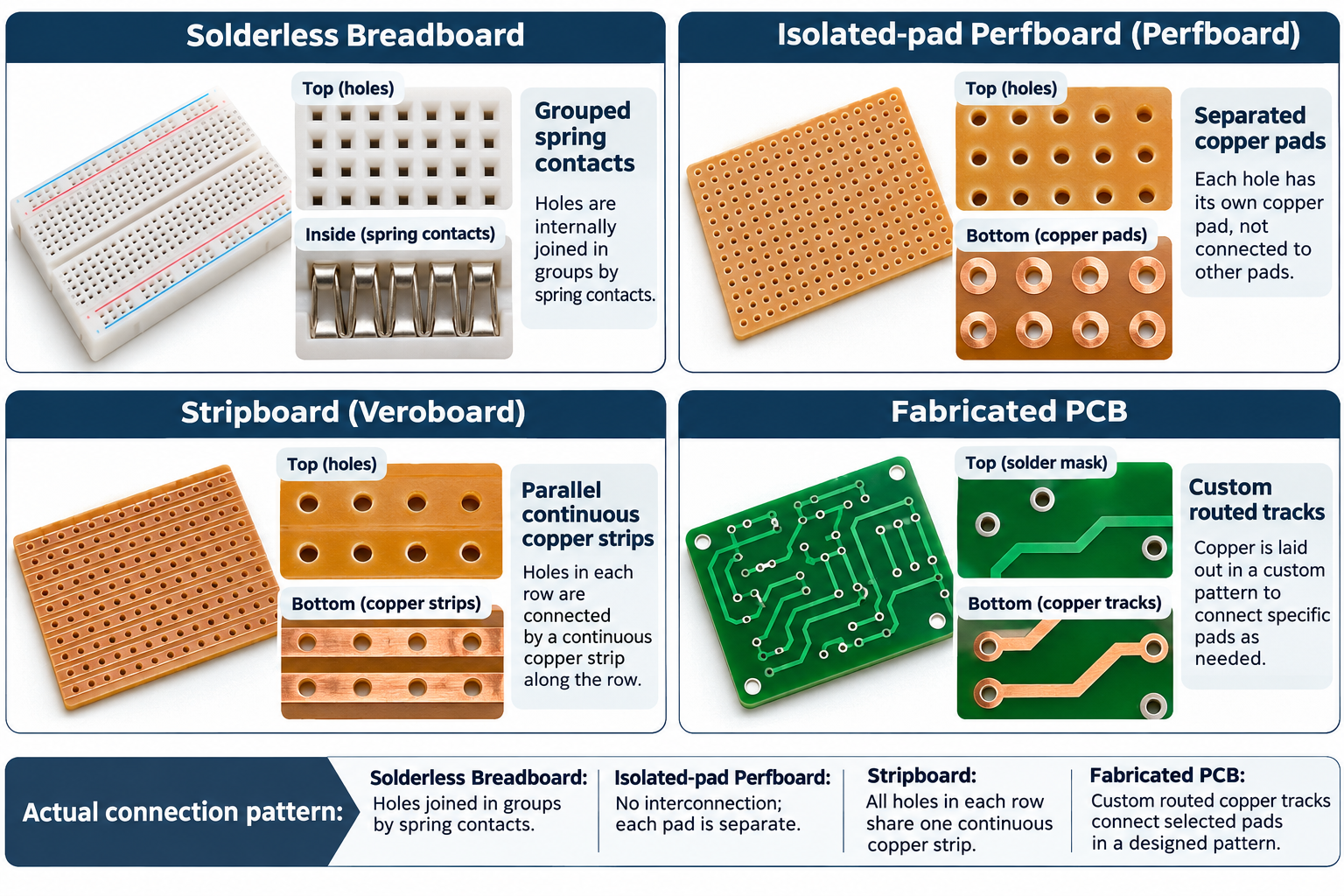
The formats differ mainly in how connections are made and controlled. A solderless breadboard uses internal contact groups. Isolated-pad perfboard provides separate pads that need the intended interconnections. Stripboard uses connected copper strips. A fabricated PCB uses a designed copper pattern and associated manufacturing outputs. Always identify the actual product’s connection pattern.
| Format | Connection basis | Useful early question | Limitation to retain |
|---|---|---|---|
| Solderless breadboard | Internal contact groups with removable connections | Can the documented concept be explored reversibly? | Does not reproduce the final routed layout |
| Isolated-pad perfboard | Separate pads with added interconnections | Can a more fixed experimental build be documented? | The name alone does not define the completed net connections |
| Stripboard | Copper strips with a product-specific arrangement | Does the available pattern suit the intended prototype? | Connectivity must be checked against the actual board pattern |
| Fabricated prototype PCB | Custom routed copper from controlled design outputs | Does the proposed PCB revision meet its defined evaluation task? | A first build is not automatically production qualification |
Adafruit’s Perma-Proto product is a useful named example of a solderable board that preserves breadboard-style connection groups. That feature does not apply to every board sold as perfboard. The supplier’s own layout information is therefore more useful than assuming that a familiar hole pattern implies familiar connectivity.
There is no universal current, voltage or frequency rating shared by all breadboards or prototyping boards. Use the actual product documentation and the engineering requirements. A format comparison should describe the structural differences, not invent performance limits that the individual board manufacturer has not supplied.
The connection pattern is part of the evidence
Two builds can follow the same intended schematic while using different physical interconnect arrangements. A prototype should therefore preserve both the intended connections and the actual implementation. Without that distinction, a successful result may be attributed to a layout that was never physically evaluated.
For a hand-wired build, identify the starting board pattern and the completed connection record. A top photograph may hide underside connections or changes made during investigation. For a fabricated board, retain the routed revision rather than relying on a schematic alone. The record should let another person identify what was actually present for the observation.
Do not assume that moving a circuit from a breadboard onto a PCB preserves every behavior. The physical layout has changed, so any layout-dependent requirement needs evaluation in the relevant implementation. This is a boundary on the evidence, not a claim that every move will cause a problem or that one format is always technically superior.
When comparing results, distinguish a changed circuit from a changed test condition. Record both. Otherwise, a later team may attribute an improved result to the new board format when the configuration or evaluation conditions also changed. A prototype is most valuable when its evidence can be interpreted, not merely when its photograph looks complete.
Separate electrical, mechanical and manufacturing questions
A board can demonstrate electrical behavior while leaving mechanical fit unresolved. It can also fit the enclosure while lacking a complete electrical evaluation. Give each question its own evidence and disposition. Combining them under one general “prototype passed” label makes the remaining work harder to see.
For mechanical review, use the whole assembly envelope. The board outline is only one part of it. Connectors, components above and below the board, access for assembly and the intended mounting arrangement can affect fit. A bare-board outline check does not automatically cover the populated assembly.
For manufacturing review, identify the actual process or handoff question. A hand-built sample may demonstrate a concept without representing the intended assembly route. Conversely, a fabricated prototype can expose questions in the release package even before it provides all the desired operating data. Record those findings against the relevant deliverable.
Use separate status fields for the three areas rather than one overall color. An electrical question may be answered, a mechanical question may need a different connector arrangement, and a manufacturing question may remain open pending a clarified output file. That record helps the next build focus on the unresolved decision instead of repeating every earlier activity.
Prepare a useful prototype PCB handoff
A fabrication or assembly request needs controlled information about the design being supplied. KiCad’s getting-started documentation separates schematic work, footprint assignment, PCB layout, checks and manufacturing outputs. These are connected stages, but one file does not replace all the others.
| Handoff item | What to identify | Question to resolve with the provider |
|---|---|---|
| Design revision | Controlled schematic and PCB revision | Which version is being fabricated or assembled? |
| Connectivity | Intended net relationships and fitted options | Are optional or unpopulated positions clear? |
| Mechanical definition | Board outline and relevant mounting features | Is the intended physical shape unambiguous? |
| Manufacturing outputs | The files required by the selected provider | Do the delivered outputs match the released revision? |
| Assembly information | Bill of materials and relevant placement or option records | Which exact parts and assembly configuration are required? |
| Material or stack requirements | The application-specific definition where relevant | Which requirements need explicit agreement rather than provider defaults? |
| Evaluation purpose | The question the returned prototype should support | What evidence will be needed after delivery? |
The provider’s requirements determine the exact file set. Gerber and drill outputs, a bill of materials or assembly information may be needed for the applicable service, but do not assume every provider accepts an identical package. Clarify naming, revision and intended scope before release rather than relying on an informal attachment list.
Electrical-rule and design-rule checks support the design workflow; they are not equivalent to proving the completed assembly’s function. Preserve relevant check results and unresolved items as part of the release decision. Avoid describing a file as production-ready merely because it was exported successfully or because one software check completed without reporting an error.
Manage revisions and investigation results
A useful prototype record connects the physical sample to its design, assembly options and observations. Give each evaluated build a traceable identity. If changes are made during development, distinguish the original released design from the modified state so a later engineer does not reproduce the wrong configuration.
| Evaluation field | Information to preserve | Why it matters |
|---|---|---|
| Sample identity | Board revision and build identifier | Connects observations to the physical item |
| Assembly state | Fitted parts, options and documented changes | Defines what was actually evaluated |
| Question | The specific behavior or fit being assessed | Prevents a narrow result becoming a broad approval |
| Conditions | Relevant setup and operating conditions from the authorized record | Makes repeated observations interpretable |
| Observation | Result as recorded, with supporting evidence | Separates what happened from the proposed explanation |
| Disposition | Answered, unresolved or requiring a design change | Directs the next build’s purpose |
Keep observations separate from explanations. “The connector does not clear the proposed enclosure in this build” is different from “the board outline is wrong.” The cause may require further review of the connector, mounting arrangement or enclosure definition. Preserving the narrow observation prevents an early explanation from becoming an unsupported design requirement.
After a change, identify which prior evidence still applies and which question needs another evaluation. A changed mechanical feature may leave some observations relevant while affecting others. The record should make that judgment explicit. Repeating every activity without a reason wastes effort; carrying every old conclusion forward without review can hide a changed assumption.
Specify handling around the actual board envelope
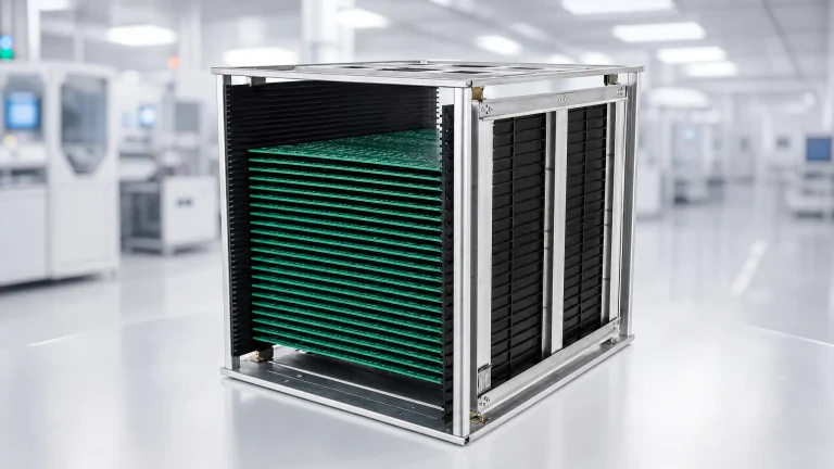
Prototype handling should reflect the physical sample, not an idealized bare-board rectangle. Consider component height on both sides, connector projections, permitted support regions and access for removal. A carrier that fits the outline may still interfere with a component or make the board difficult to retrieve safely.
For boards moving between evaluation and assembly areas, retain identity and separation requirements alongside the physical dimensions. Different revisions should remain distinguishable, especially when the outlines are similar. A carrier label can help connect a sample to its record, but it is not a substitute for the controlled design and build identification.
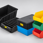
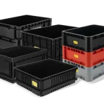
ESD magazine racks for PCB handling can be considered where a supported, separated board route is appropriate. Confirm compatibility using the actual board and component envelope, support arrangement and applicable material evidence. The category does not establish universal fit, electrical qualification or a PCB manufacturing service.
EOS/ESD Association guidance provides broader context for controlled handling of sensitive electronics. Keep those controls connected to the component and assembly requirements. A successful prototype demonstration and a suitable handling route are complementary pieces of evidence: one does not automatically establish the other, and neither should be represented by an unsupported product guarantee.
Questions about prototype circuit boards
Should every project begin on a solderless breadboard?
No. Choose the platform that can answer the first meaningful development question. A reversible connection experiment may suit a breadboard, while a question about a particular layout or enclosure may require a different prototype. Define the evidence needed before selecting the format rather than treating one format as a mandatory starting point.
When is a prototype ready to hand to another team?
When its identity, intended configuration, relevant design outputs and observation record are clear enough for that team’s task. Readiness depends on the purpose of the handoff. An evaluation sample, a fabrication package and a production release need different deliverables. State which handoff is intended and list the unresolved items with it.