

A silicon controlled rectifier, or SCR, is a controlled, unidirectional thyristor with an anode, cathode and gate. A suitable gate condition can start conduction when the device is appropriately biased. Once conduction has latched, removing the gate signal alone is normally not a general command to turn a conventional SCR off.
The main reading challenge is separating triggering, latching and holding. These describe different parts of the operating sequence and appear as different data-sheet parameters. This guide explains that sequence, compares related device names and provides a rating-review checklist. It does not provide power-circuit construction, energized testing or repair instructions.
What a silicon controlled rectifier does
An SCR combines rectifying behavior with controlled turn-on and latching behavior. Its semiconductor structure is commonly described as PNPN. The main current path is associated with the anode and cathode, while the gate provides the triggering function in normal controlled operation. Calling it simply a three-terminal diode leaves out the state-dependent behavior that makes it useful.
The word “controlled” also needs a boundary. It does not mean that the gate continuously commands both on and off states in the same way as every other semiconductor switch. A conventional SCR can remain conducting after the original gate excitation ends, provided the main-current conditions sustain that state. That distinction is central to understanding its data sheet.
| Concept | What it describes | What it does not establish |
|---|---|---|
| Rectification | The conventional device’s directional main-current behavior | Bidirectional behavior equivalent to a TRIAC |
| Gate triggering | Initiating conduction under the required conditions | That conduction has necessarily become self-sustaining |
| Latching | Establishing a sustained conducting state | A universal current value for all SCRs |
| Holding | Maintaining the conducting state once latched | That the gate is a general turn-off input |
Littelfuse’s application note distinguishes these operating concepts, while the Monolithic Power Systems learning material explains the underlying controlled latching device. Those sources support the conceptual sequence here. They do not provide ratings for an unidentified part or approval for substituting one package for another.
Anode, cathode and gate have different jobs
The three terminal names identify electrical functions. They do not specify a universal physical lead order. Read the manufacturer’s actual package drawing, including its view orientation, before interpreting a part’s pins. A generic schematic symbol is not enough to identify an unmarked device on a workbench.
The anode-to-cathode path carries the main current in normal forward conduction. Gate triggering is considered relative to the cathode and under the conditions specified for the device. A gate parameter therefore must not be compared casually with a main-current rating. They refer to different functions, even if both happen to be expressed in amperes.
This separation helps when reading a supplier’s abbreviated table. A column labeled “trigger current” is incomplete if it does not state which parameter and conditions are meant. Likewise, a high headline main-current value says little about the gate requirements or the thermal arrangement needed for a particular application.
For receiving and engineering review, retain the full part number, package suffix and document reference. If the physical marking is abbreviated, use a supported manufacturer identification record rather than guessing from a familiar package shape. Correct identity comes before interpreting the numerical ratings, because a precise reading of the wrong data sheet is still the wrong selection basis.
Separate gate triggering, latching and holding current
Gate trigger current, commonly written IGT, concerns the gate condition needed to initiate triggering under specified conditions. Latching current, IL, concerns establishing the sustained main-current state after gate excitation. Holding current, IH, concerns maintaining conduction once the device has already latched. They belong to different moments in the sequence.
| Parameter | Question to ask | Comparison mistake to avoid |
|---|---|---|
| IGT | What gate trigger condition is specified? | Treating it as the continuous load-current rating |
| IL | What main current is needed to establish latching under the specified conditions? | Assuming any triggered current immediately guarantees a latch |
| IH | What current condition maintains the already latched state? | Using it as an interchangeable substitute for IL |
| Related voltage, time and temperature conditions | Under what circumstances is the parameter defined? | Comparing isolated numbers from different conditions |
The distinction between IL and IH is especially useful. A state that can be maintained after latching may not be sufficient to establish latching in the first place. Read the sequence as well as the parameter definitions. Looking only for the smallest number can conceal that the values answer different questions.
Littelfuse AN1002 is a historical application note used here for these stable definitions, not as a current product-rating source. For a purchase or design decision, consult the exact device’s current documentation. Preserve the stated conditions and value type rather than promoting a typical teaching value into a guaranteed requirement.
A hypothetical state-transition example
Assume an invented teaching device with latching current IL of 30 mA and holding current IH of 10 mA. These values are chosen solely to make the states easy to distinguish. They are not the ratings of a CH-ESD product, a recommended gate drive or instructions for a physical test.
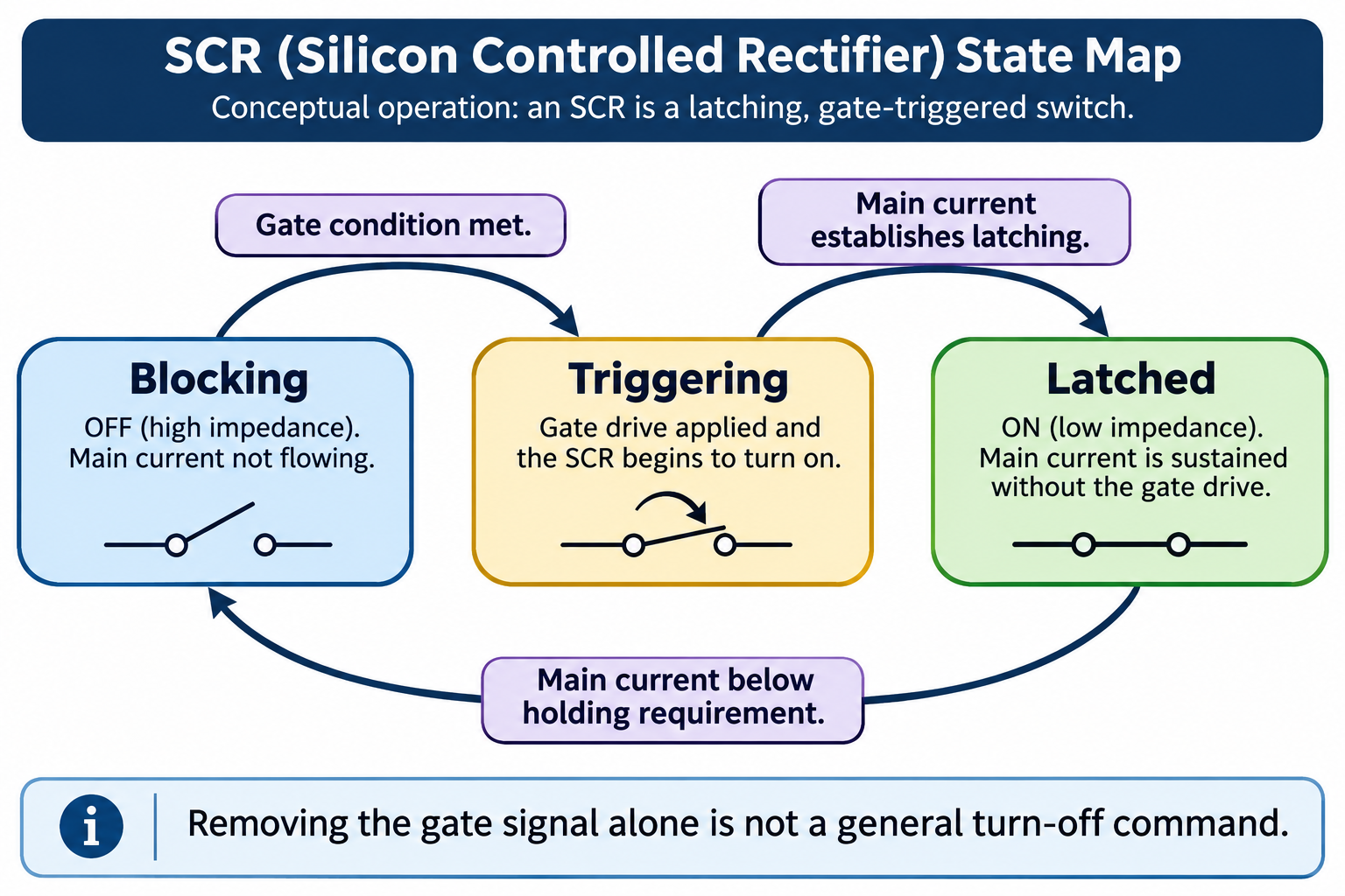
In this simplified scenario, suppose the appropriate gate condition is present and main current reaches 40 mA, sufficient to establish the assumed latch. If main current subsequently becomes 20 mA after the gate excitation ends, the device can remain latched because that current exceeds the assumed 10 mA holding requirement.
Now consider 20 mA before latching is established. Although 20 mA exceeds IH, it is below the assumed 30 mA IL. The holding-current comparison alone cannot prove that the initial latch will be established. The sequence matters: the same numerical current can have a different significance before and after the conducting state is established.
If the already latched main current falls below the assumed holding requirement, the sustaining condition is removed in this idealized account. Real turn-off behavior also involves the device’s specified conditions and timing. The example explains why the parameters are different; it does not replace the full device model or establish a switching circuit design.
SCR, diode, transistor and TRIAC are not synonyms
Related semiconductor devices can appear in similar packages while having different operating principles. A conventional SCR is unidirectional in its normal controlled main-current behavior. A TRIAC is a different bidirectional device class. Similar terminology in a distributor category does not make them interchangeable.
| Device name | Relevant distinction in this comparison | Selection consequence |
|---|---|---|
| Rectifier diode | No separate gate-trigger terminal in the ordinary two-terminal device | Does not provide the same controlled latching function |
| Conventional SCR | Controlled triggering with latching main-current behavior | Trigger, latch, hold and turn-off conditions need separate attention |
| TRIAC | Bidirectional controlled device class | Do not assign conventional SCR behavior or pin assumptions automatically |
| Transistor | A broad category with different control behavior depending on type | “Three terminals” is not a functional equivalence statement |
| Gate-turn-off thyristor | A distinct device class designed for a different control capability | Do not transfer that capability to every SCR |
The comparison is about device identity, not a recommendation to replace one with another. A circuit designed around one behavior may depend on characteristics absent from the proposed alternative. Procurement should flag the class change rather than describe it as a higher-rated version of the same component.
Also retain the manufacturer’s exact terminology. Abbreviations in purchasing notes can lose the distinction between a device family and a particular approved part. Record the source document and the specific proposed substitution so engineering can assess the actual change, including the required operating sequence.
Read voltage, current and thermal ratings together
A headline current value is not a complete SCR selection rule. Voltage ratings, main-current definitions, gate parameters, timing and thermal information belong to the same review. The conditions next to a rating explain what that number represents. Omitting those conditions can make two devices look comparable when the supplied values describe different duties.
| Data-sheet area | What to preserve in the comparison | Useful review question |
|---|---|---|
| Device identity | Exact part, package and document revision | Does the evidence concern the proposed supplied device? |
| Voltage ratings | Rated quantity and stated conditions | Which voltage condition is the number describing? |
| Main current | Definition, value type and applicable duty | Is this the same kind of current rating in both documents? |
| Gate and latching | IGT, IL, IH and their conditions | Are start, latch and sustain requirements being kept separate? |
| Timing | Relevant manufacturer-defined conditions | Does the application require behavior not covered by the headline rating? |
| Thermal information | The applicable arrangement and temperature basis | Is the proposed comparison using equivalent conditions? |
| Package | Terminal assignment and mechanical drawing | Is electrical and physical identity actually established? |
STMicroelectronics maintains device-specific SCR documentation that illustrates why the exact data sheet is the right next source. This guide does not select a current rating, cooling arrangement or gate network. Those decisions require the actual part and application, rather than values inferred from a generic description.
Keep unresolved entries visible. A missing condition is not a matching condition. If a supplier offers a short summary, request the underlying manufacturer document before treating the summary as substitution evidence. An approval record should state the assembly or application to which the decision applies, so a later buyer does not extend it to unrelated equipment.
Preserve component identity and handling requirements
The component’s electrical approval and its physical handling are separate decisions. An approved SCR can still be mixed with unapproved stock if identity is lost during receiving or assembly. Retain the full part number, lot or receiving reference, approved source and destination assembly with the material as it moves through the process.
For a handling review, record the actual body and lead envelope, permitted support arrangement and applicable component documentation. A carrier should be selected around the physical item and its approved handling controls. It should not be treated as evidence that the part has the required electrical ratings or that a proposed substitute is equivalent.
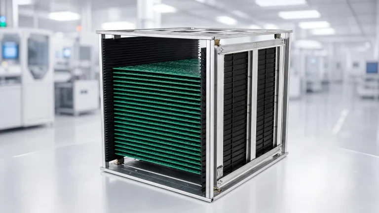
ESD trays for electronic component handling can be considered when an appropriate carrier is needed. Confirm the configuration and relevant material evidence for the intended item. This is a handling connection to the topic, not a claim that CH-ESD manufactures SCRs or that a tray supplies electrical isolation for a powered circuit.
Use EOS/ESD Association guidance as broader context for a controlled electronics-handling route. The individual device and the site’s approved requirements determine the applicable precautions; a family name does not establish universal sensitivity. Connecting component identity, documentation and handling records gives production a clearer handoff than a loose bag labeled only “thyristor.”
Questions about SCR operation
Why can an SCR stay on after the gate signal is removed?
Once the conventional device has latched, main-current conditions can sustain conduction independently of the original gate excitation. That is why triggering and holding are separate concepts. Removing the gate signal is normally not a general off command. The actual part’s operating and turn-off conditions still control its behavior.
Can I choose an SCR only by its current rating?
No. The particular current definition and conditions must be understood alongside voltage, gate, timing, thermal and package information. A larger isolated number does not establish suitability or interchangeability. Use the exact manufacturer documentation and the approved application requirements to define what must be compared.
References
- Littelfuse: Gating, Latching and Holding of SCRs and Triacs, AN1002 (2008)
- Monolithic Power Systems: Thyristors
- STMicroelectronics: Thyristor Documentation
- EOS/ESD Association: Control Procedures and Materials