
EMI shielding reduces unwanted electromagnetic coupling by placing an appropriate barrier around a source, a sensitive circuit, or a connecting cable. Its effectiveness depends on frequency, material, openings, electrical connections and the finished assembly. Buying a conductive material is only one part of the design.
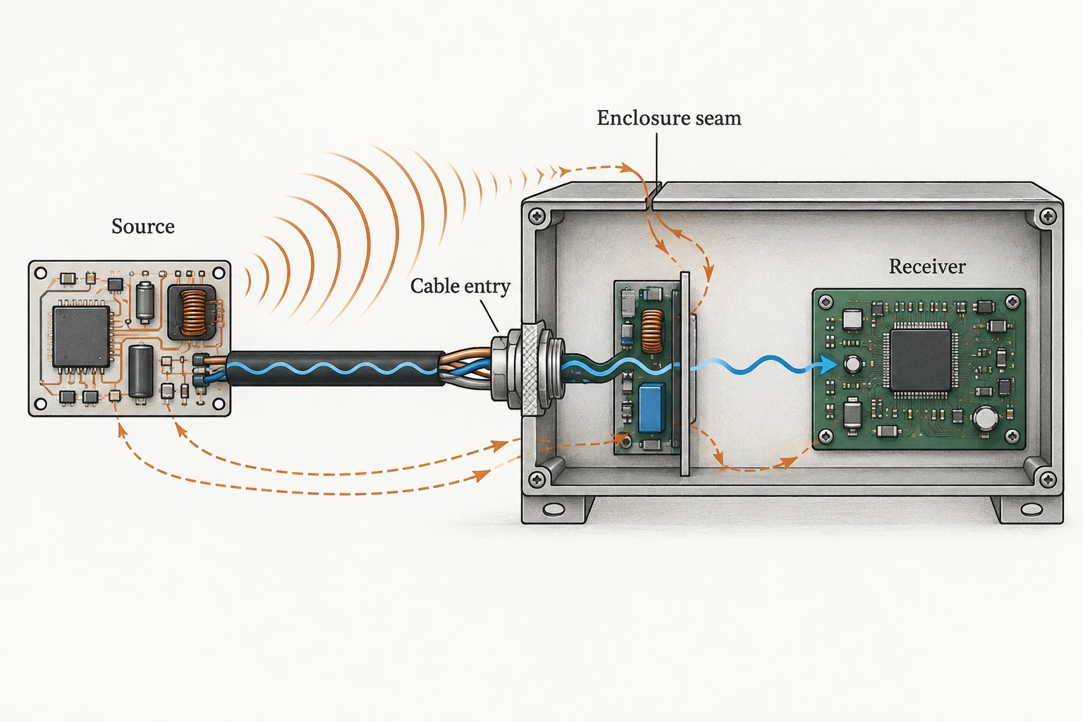
For an electronics manufacturer, the useful question is where interference enters or leaves the system. A shield around a board will not necessarily solve noise travelling along a cable, and a shielded cable cannot correct every problem inside the enclosure.
Start EMI shielding with the interference path
Identify the source, the affected circuit and the path between them. A switching circuit may disturb a nearby sensor; a cable may receive external interference or carry noise away from the equipment. Molex explains that cables can behave as unintended antennas and that shield construction influences their interference performance.
Consider a hypothetical sensor whose readings change when an adjacent drive starts. The observation identifies a correlation, not a proven coupling path. Record the operating modes, cable configuration and affected signal before choosing between enclosure changes, cable shielding, filtering or layout work. This keeps the design investigation focused on a repeatable symptom.
Compare methods by the boundary they protect
| Method | Boundary addressed | Question to resolve |
|---|---|---|
| Conductive enclosure | Space around the circuit assembly | How are seams, vents and removable panels handled? |
| Cable shield | Coupling involving a cable run | Does the connector preserve the intended shield connection? |
| Local shield over a circuit | Coupling near a sensitive or noisy section | Can interference bypass it through traces or connections? |
| Filtering and layout changes | Specific circuit or connection paths | Do these address the identified path without impairing the signal? |
These measures can complement one another. The comparison is not an attenuation ranking: no material or arrangement has a universal performance value independent of its test conditions.
Choose materials with the assembly in mind
Metal housings, conductive foils and cable braids solve different mechanical problems. A rigid housing must accommodate access and ventilation. A flexible cable needs a construction that tolerates its movement and routing. Molex describes foil, braid and spiral shield constructions, including the possibility that movement separates strands in some arrangements.
Ask suppliers how the proposed shield fits the actual geometry and service conditions. Thickness, coverage, joining method, corrosion compatibility and repeated opening all deserve attention. Avoid selecting copper, aluminium or a conductive coating simply because its material name sounds more effective. The question is whether the proposed assembly provides the required performance at the relevant frequencies.
Seams and cable terminations need their own review
A shield is interrupted wherever the equipment needs an opening. A connector, lid joint or vent can therefore matter as much as the main wall. Analog Devices discusses shielding alongside grounding, filtering and physical circuit construction in its hardware-design guidance. The treatment of low-frequency interference is not automatically the right solution at higher frequencies.
For that reason, a blanket rule to connect every shield at one end, or at both ends, is not a complete design method. Document the signal type, relevant frequency range, interface design and intended connection. Have the equipment designer evaluate the whole path rather than applying a cable rule in isolation.
What to ask for before accepting a shielding claim
A useful test record identifies the specimen, configuration, frequency range, method and result. If a supplier provides a material coupon result, ask how it relates to the finished housing with its real openings. If the test used a particular cable and connector, record them with the product configuration. A result from one arrangement should not silently become a claim for every variant.
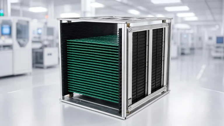
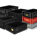
Keep production handling separate from operating EMI performance. CH-ESD’s ESD storage and transfer boxes support a different handling task; a conductive container is not automatically a validated EMI enclosure. Match handling equipment to the components and workflow, while retaining separate evidence for the finished product’s electromagnetic performance.
The practical deliverable is a documented design question: which source and receiver are involved, which path is being controlled, and which assembled configuration must be evaluated? That gives suppliers and test engineers something more useful than a request for the “best shielding material.”