

The main types of circuit boards used in drones are flight-controller boards, electronic speed controllers, power-distribution and power-management boards, navigation modules, communications boards, payload electronics and, where needed, companion computers. These names describe functions. Rigid, flexible, rigid-flex and multilayer describe how a PCB is constructed.
A drone does not necessarily have a separate board for every function. One assembly may combine several jobs, while another aircraft distributes them among replaceable modules. To identify a drone circuit board correctly, determine what it does before deciding what physical construction or replacement specification it needs.
The distinction is useful for purchasing, inspection and board handling. Two assemblies can share a mounting outline but have different functions; two boards with the same function can use different layouts and interfaces.
Types of circuit boards used in drones, by function
Start with the system role. The following map identifies common jobs without prescribing a universal board count.
| Board or module | Main job | What to identify before comparing parts |
|---|---|---|
| Flight controller | Runs the autopilot and interfaces with sensors and control outputs. | Supported hardware, firmware, interfaces and mounting arrangement. |
| Electronic speed controller (ESC) | Uses a control signal to regulate power delivered to a motor. | Motor/controller compatibility and the manufacturer’s specified power requirements. |
| Power-distribution board (PDB) | Distributes the battery supply to required branches. | Actual distribution arrangement, connectors and supported loads. |
| Power module or management board | May provide regulated controller power and battery voltage/current information. | Which supply and measurement functions the particular module includes. |
| Navigation or sensor module | Provides measurements such as position, direction or other vehicle-state inputs. | Sensor function, interface and placement requirements. |
| Receiver or communications board | Exchanges control information or operational data with other equipment. | Protocol, supported interfaces and the equipment it communicates with. |
| Payload electronics | Supports the aircraft’s application-specific equipment. | The payload’s actual function and its integration documents. |
| Companion computer | Provides additional onboard computing alongside a flight controller. | Compute task, data interface and division of responsibilities. |
Flight controller: the control role
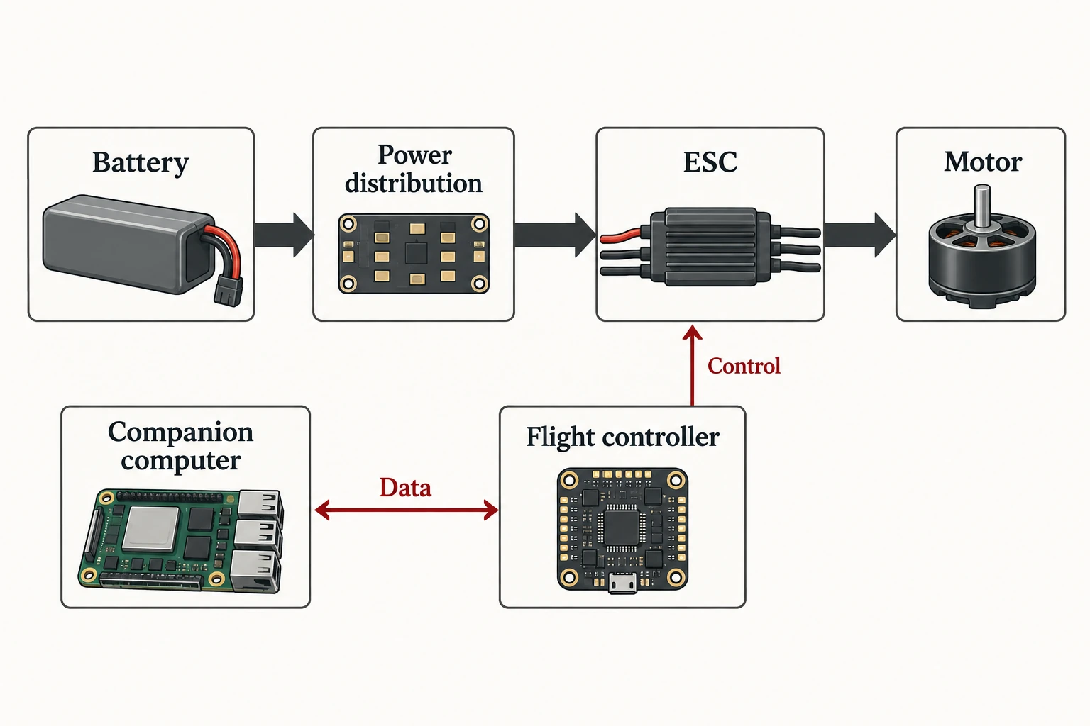
The flight controller is the autopilot hardware. PX4 describes it as the board on which its flight-stack firmware runs. It receives information from sensors and connects to outputs used to control the aircraft.
When identifying one, use its actual hardware documentation. A board with a processor and connectors is not automatically a compatible flight controller. Record the model, supported firmware and required interfaces rather than making the identification from appearance alone.
ESC and power boards: separate jobs in the power path
An ESC is not simply another name for a flight controller. It takes a controller signal and controls the power delivered to a motor. A PDB instead distributes the supply. A power module may add regulation and voltage/current measurement.
Those functions can appear in different combinations. Ask what a particular assembly contains before treating “power board,” “ESC board” and “distribution board” as interchangeable purchasing descriptions. The component manufacturer’s documents govern the actual electrical compatibility.
Navigation, communications and payload boards
Some electronics supply information to the controller; others carry information between the aircraft and external equipment. Navigation modules, radio receivers and telemetry equipment therefore belong to different identification questions, even when each arrives as a small populated PCB.
Payload electronics depend on the intended application. Identify the payload first, then document how it exchanges data and receives power. Avoid turning a list of possible modules into a claim that every drone requires each one.
Companion computers: additional computing
A companion computer adds onboard computing and communicates with the flight controller. PX4 distinguishes this role from the controller itself. This distinction helps when an assembly includes both a control board and a computing module: they can be part of the same platform while performing different jobs.
Rigid, flex, rigid-flex and multilayer describe construction
Once the function is clear, describe the physical board separately. A “multilayer flight controller” combines a construction description with a functional description; the two terms do not compete as alternative board types.
| Construction term | What it describes | Question for the drawing or supplier |
|---|---|---|
| Rigid PCB | A board with a rigid supporting structure. | What outline, thickness, support and mounting features are specified? |
| Flexible PCB | A circuit built on a flexible structure. | Which portions may flex, and what handling conditions are approved? |
| Rigid-flex PCB | Rigid sections integrated with flexible sections. | Where are the transitions, supported regions and permitted bends? |
| Multilayer PCB | A board with multiple copper layers in its stackup. | Which stackup and revision belong to the required assembly? |
These terms alone do not establish the right construction for a drone. The design’s electrical, mechanical and manufacturing requirements determine the specification. There is no responsible universal answer such as “all drone boards need the same layer count.”
For an incoming assembly, the practical output is an identified drawing and revision. If a supplier proposes a construction change, ask the design owner to evaluate it against the actual requirements rather than treating a similar outline as evidence of equivalence.
A practical identification example
Consider a proposed modular multirotor with a flight controller, separate motor-control electronics, a power-distribution arrangement and a navigation module. The parts list should describe the job and identity of each assembly independently.
The controller entry can identify its approved hardware revision and required connections. The motor-control entry can identify the ESC assembly and compatibility documents. The power entry can distinguish distribution from measurement or regulation. The navigation entry can specify the module and its interface.
If a replacement combines previously separate functions, revise the system map before comparing prices. One purchase line may replace several old lines, but the integration requirements still need review. Conversely, a board that physically fits the mounting location may not serve the same function.
This example is an identification method, not a tested aircraft design. Its value is the sequence: define the job, identify the assembly, check its interfaces, and then evaluate construction and handling.
What to record before purchasing or handling drone boards
A useful board record connects the system role to a specific assembly and a physical envelope.
- Function: Which controller, power, sensing, communications or payload job does it perform?
- Identity: What model, assembly number and revision are required?
- Interfaces: Which connectors and supported connections must match the integration documents?
- Geometry: What are the outline, mounting points and component clearances?
- Configuration: Does the delivered item include the required accessories and integrated functions?
- Handling: Where may the assembly be supported, and what must stay clear during storage and transfer?
The handling question is distinct from the electronics specification. A board outline does not reveal the full component envelope, and a flexible region should not be treated as an arbitrary support surface. Send the assembly drawing and approved support conditions to the handling-product supplier.
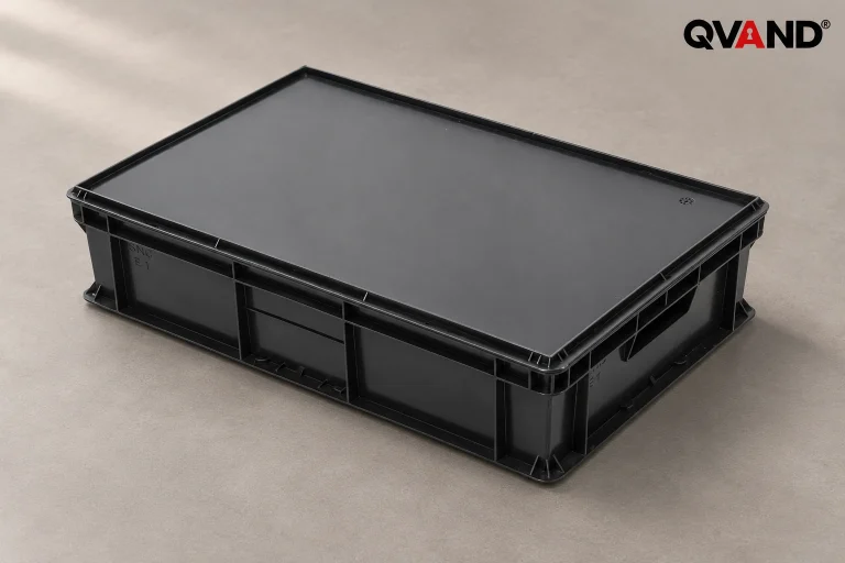
Quan Dun’s ESD tray range is relevant to that physical handling task. Match a proposed tray to the board footprint, component height, access direction and support requirements. An ESD tray is not evidence of aircraft qualification or a substitute for the board manufacturer’s handling instructions.
Keep the functional list, approved assembly documents and handling specification together. That gives the next purchasing or inspection review a clear object to compare, rather than a generic request for a “drone PCB board.”
References
- PX4: flight-controller hardware — the autopilot-hardware role.
- PX4: power modules and distribution boards — supply, distribution and measurement functions.
- PX4: ESCs and motors — the controller-signal and motor-power relationship.
- PX4: companion computers — additional onboard computing.
- PX4: basic vehicle concepts — sensors, control and peripheral roles.
- JLCPCB: rigid-flex construction — distinction between rigid and flexible regions.