
A cold soldering joint is a connection that has not formed adequately during soldering, commonly because insufficient heat reached the surfaces needed for proper wetting. It may produce poor or intermittent electrical behavior. However, a dull surface alone does not prove that a joint is cold, and a continuity beep alone does not prove that it is acceptable.
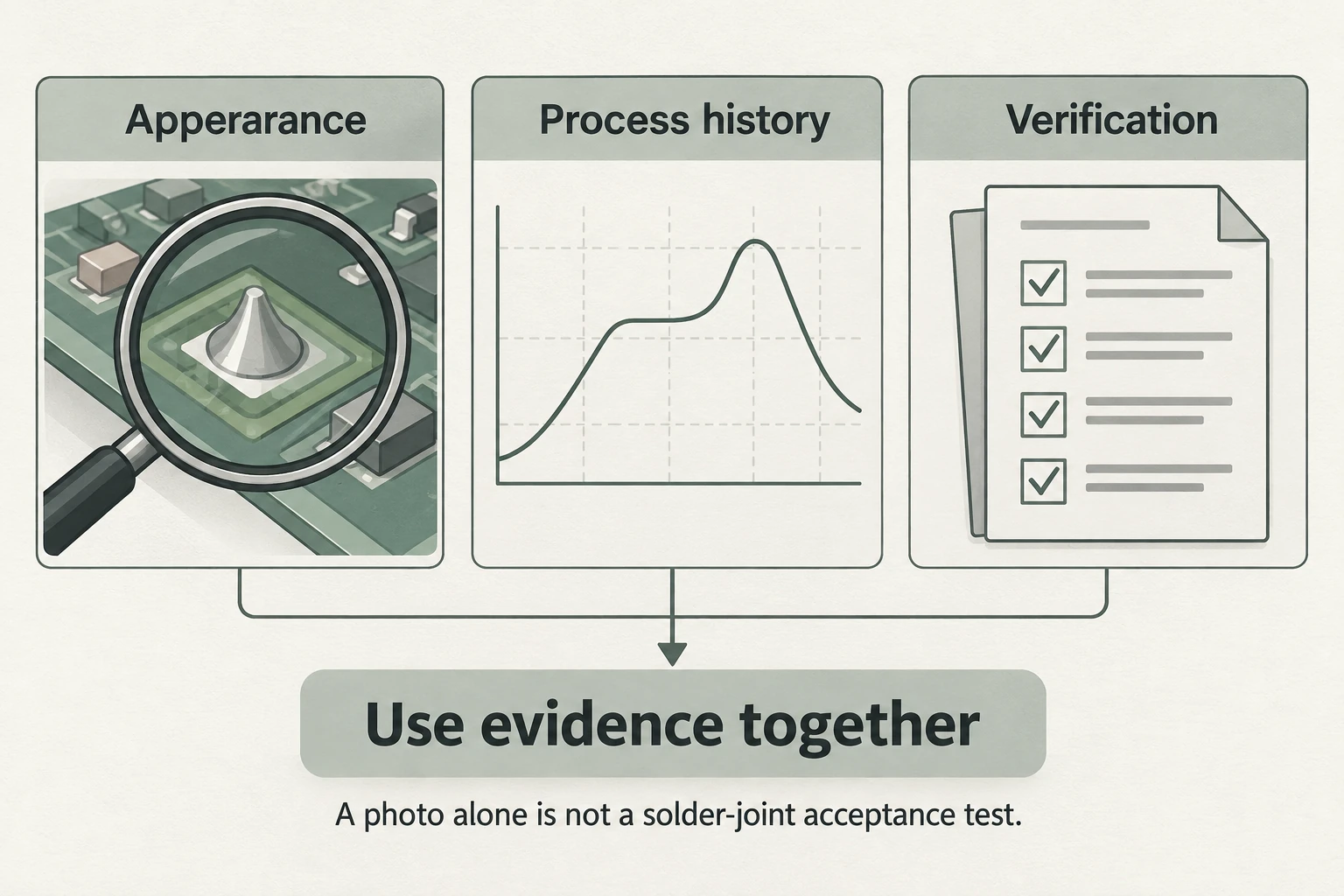
Identify the observed condition before choosing a repair. The useful assessment combines the joint’s appearance, the alloy and process history, and the verification required for that assembly.
What a cold soldering joint can look like
Insufficient wetting is a reason to investigate. Solder may appear to sit on a surface without making the intended connection to the lead and pad. Geometry, access and lighting affect what an inspector can see, so a single photograph is a limited record.
Hakko’s technical guidance connects inadequate heat transfer with insufficient wetting. It also identifies the heat-sinking effect of some PCB designs. A temperature setting at the tool is therefore not the same thing as evidence that the joint received the needed heat.
| Observation | Reason to investigate | What it does not establish |
|---|---|---|
| Poor apparent wetting | Check surfaces, materials and thermal process | The exact cause from appearance alone |
| Dull or lightly crazed surface | Identify the alloy and expected finish | Automatic failure of a lead-free joint |
| Intermittent electrical behavior | Correlate the fault with the affected connection | That solder is necessarily the only fault |
| A continuity indication | Record the method and conditions | Mechanical integrity or long-term acceptance |
Why dull lead-free solder is not automatically defective
Kester explains that tin-silver-copper solder can have a duller or slightly crazed appearance compared with traditional tin-lead solder. That appearance can be characteristic of the alloy. Applying a “shiny equals good” rule across different alloys can therefore misclassify a joint.
The reverse assumption is equally unhelpful: a bright surface is not a full record of the connection beneath it. Keep the visual description separate from the acceptance decision. “Dull surface on this alloy” is an observation; “failed joint” requires the applicable evidence.
Causes to investigate before choosing rework
Start with the thermal process, surface condition and material identification. Hakko discusses inadequate heating, equipment conditions and PCB design as possible contributors. The same guidance also cautions that excessive heating can damage components or lift PCB features.
This creates an important boundary: “add more heat” is not a complete repair instruction. The assembly, solder alloy, flux and approved process determine the appropriate rework conditions. Copying a temperature from an unrelated example can obscure the original problem and introduce another one.
Process records help distinguish a single anomalous joint from a repeated condition. Record the board and component references, the material or alloy information available, and whether similar joints from the same operation show the same observation. A repeated pattern provides a different investigation path from an isolated damaged connection.
Why a continuity beep is insufficient
Vicor’s application note for its power modules explicitly explains that a cold connection need not be electrically open and cannot be diagnosed by a simple continuity check. The useful general lesson is the limit of that observation, not the transfer of the note’s historical assembly criteria to every modern board.
A beep records the meter’s response under the test conditions. It does not document wetting, mechanical condition or behavior throughout the assembly’s operating environment. Where a continuity result is part of a controlled test, retain it as one item of evidence rather than the whole acceptance decision.
What to record before and after a repair
A rework handoff should identify the assembly revision, component reference, exact observed condition and relevant process information. State what is known and what remains uncertain. “Joint at connector pin appears poorly wetted” gives the technician more usable information than “bad solder everywhere.”
After approved rework, the responsible technician should document the work performed and the inspection or functional verification required by the assembly’s applicable criteria. A new photograph can record appearance; it should not silently replace the specified verification.
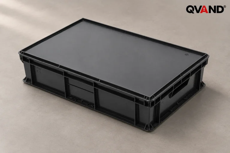
Keeping suspect and accepted assemblies separated also prevents status confusion. Quan Dun’s ESD tray options can be assessed for board support and handling, with clear identification attached to the actual assembly record. A container does not repair a joint or establish acceptance.