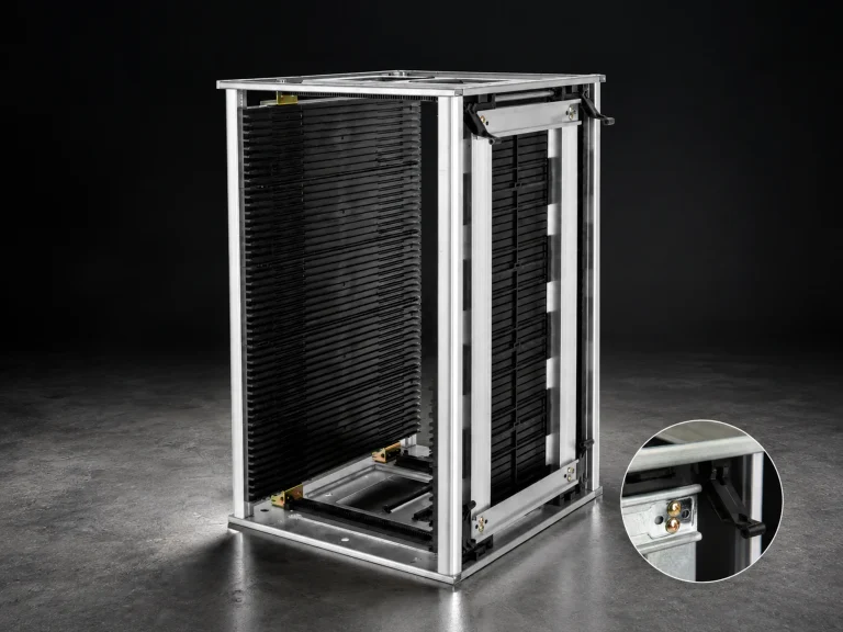


An ESD safe tray should be selected from the component, access pattern, and movement route rather than from the tray name alone. The useful question is whether the tray keeps the part supported and identifiable while operators load, inspect, move, and remove it. Material or resistance language must then be confirmed for the actual tray construction and the process where it will be used.
Begin with the ESD tray product family as a route for comparing formats. Before requesting a quote, record the component envelope, quantity per tray, required access, divider or cavity pattern, stacking or cart movement, and evidence needed for the finished handling setup.
1. Fit the ESD safe tray to the component and access pattern
Fit has two parts: the component must be supported, and the operator must be able to retrieve it without touching a sensitive feature or disturbing adjacent parts. List the largest package or board envelope, protruding connectors, exposed surfaces, orientation, and the direction of removal. If a tray is used for several variants, define the variant groups instead of assuming one cavity pattern works across all parts.
Access also determines whether a flat tray, grid tray, cavity tray, or tray with a liner is appropriate. A high-count grid can improve separation for small items, while a wider support area may suit boards or assemblies that need controlled placement. The correct choice is the one that makes loading, inspection, and removal repeatable in the real workcell.
| Tray question | Evidence to collect |
|---|---|
| How is the part supported? | Cavity, divider, liner, edge support, and contact restrictions |
| How is it removed? | Top access, drop side, one-hand access, or tool-assisted handling |
| Where does it travel? | Shelf, cart, rack, receiving area, or repeated line-side movement |
2. Treat tray material and resistance as evidence questions
The phrase ESD safe tray describes an application goal, not a universal numeric result. Ask what material family and construction are proposed, which surfaces contact the component, and what test method or documentation applies to the finished tray. When a liner, divider, coating, or insert is part of the proposal, evaluate the complete tray configuration and ask the supplier to document the contact conditions; a general ESD standard does not replace configuration-specific evidence.
Keep the tray’s mechanical job separate from its electrical role. The tray may need to protect edges, control orientation, allow visual inspection, or fit a carrier. These requirements can affect thickness, wall shape, divider geometry, and cleaning or handling practice. Do not infer compliance, resistance, or durability from a photograph or color.
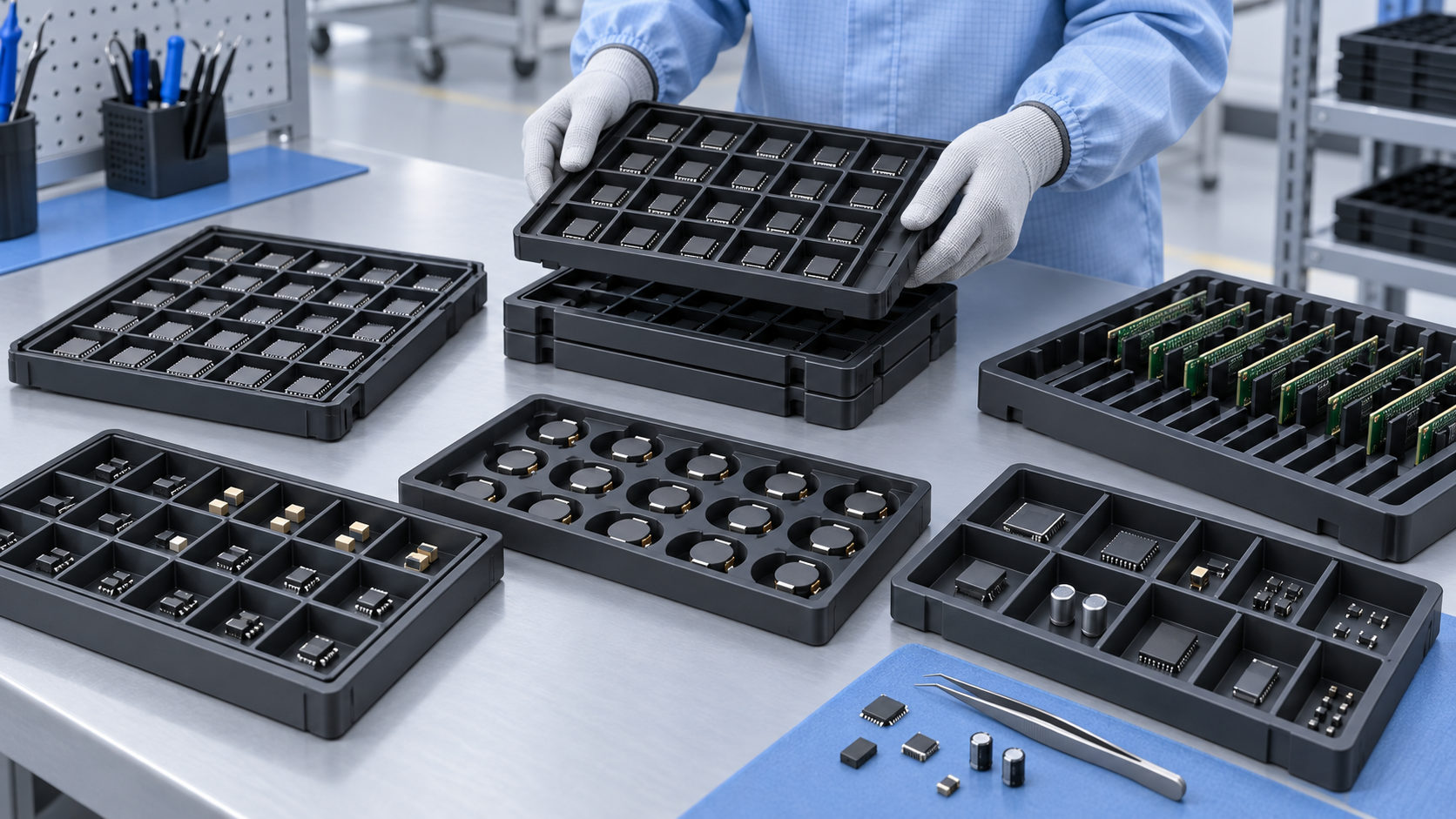
3. Review stacking, movement, and replenishment
A tray that works at a bench may behave differently on a cart or in a rack. Describe the movement route, how trays are stacked or separated, whether a lid or cover is used, and how operators identify a full or partial tray. If the tray is moved between departments, include handoff points and the risk of mixed variants or lots.
For chip or board handling, the IC tray product route may be a useful comparison point, but the final choice still depends on the part family and process. Ask for sample inspection criteria covering fit, retrieval, orientation, separation, and the condition of the tray after normal movement.
4. Build a clear tray selection request
Send the supplier one compact request with:
- Contents: component family, envelope, quantity per tray, loose or packaged state, and fragile features.
- Access: top, side, drop-side, or tool-assisted retrieval; withdrawal frequency; and one-hand needs.
- Organization: cavity or divider layout, label position, variant separation, and replenishment method.
- Route: fixed shelf, line-side station, cart, rack, receiving area, or repeated movement between departments.
- Evidence: material classification, resistance or test basis where relevant, drawing revision, sample check, and conditions attached to the result.
The request should leave configuration-specific values for the supplier to confirm. That makes the tray decision traceable and keeps the article’s general guidance from being mistaken for a product specification.
Approve the tray with a representative sample, not only from a photograph. Test loading, retrieval, component separation, stacking or cart movement, label visibility, cleaning or return, and every handoff when the tray is shared across operations. Record the drawing revision and review conditions so the selected tray remains traceable when the part family or handling route changes.