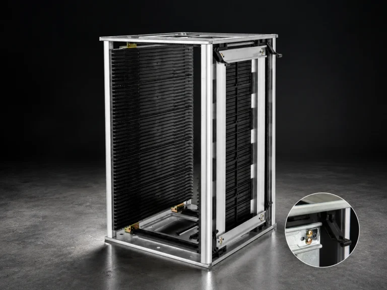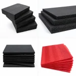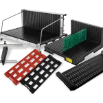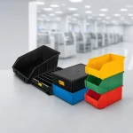


ESD kitting trays should make the correct parts available in the correct sequence while preserving identification and the required ESD handling route. A tray that merely holds everything can still create mixed lots, hidden shortages, difficult picking, or unsupported component contact.
Build the layout from the bill of materials, assembly sequence, component envelope, and replenishment method. Then verify the loaded tray through storage, movement, handoff, and return. The result should be a controlled kit, not an attractive but ambiguous grid.
1. Define ESD kitting trays from the kit
Start with one work order or assembly unit. List each component, quantity, package state, lot or date-code rule, orientation, fragile feature, and point of use. Mark components that must stay sealed until they reach a protected workstation and components that may share a compartment only when mixing cannot affect identity or quality.
Decide who owns completeness at each handoff. The warehouse may pick the kit, a material handler may move it, and an operator may consume parts in sequence. If the tray returns for replenishment, define who counts residual parts and how an incomplete or mixed kit is isolated.
| Layout input | Tray decision | Approval check |
|---|---|---|
| Component envelope | Cavity or compartment size and clearance | Largest approved package fits without lead, connector, or surface interference |
| Quantity and sequence | One position per item, group, or assembly step | Operator can identify and pick without crossing unrelated parts |
| Lot control | Dedicated position, removable cup, or separate tray | Mixed lots and returned parts remain identifiable |
| Replenishment | Fixed labels, count marks, and empty-position visibility | Shortage and wrong-part conditions are visible before release |
| Route | Cover, stack, tote, cart, or hand-carry requirement | Loaded tray remains stable and readable at every handoff |
2. Build the layout from the bill of materials and sequence
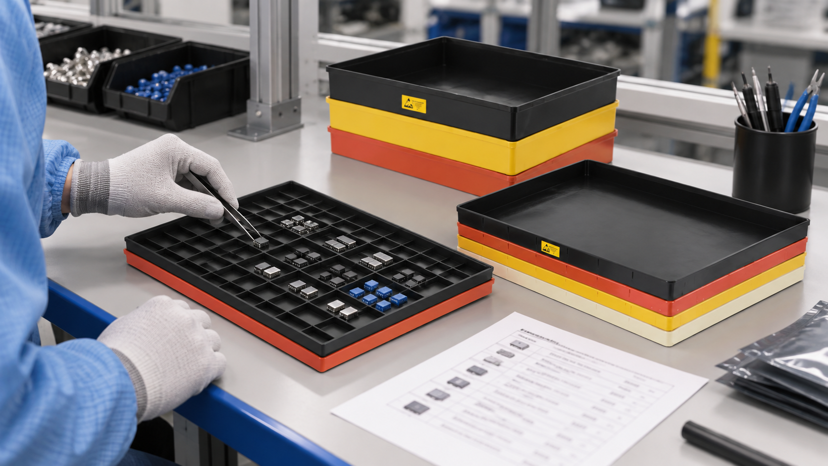
Arrange high-use or first-use parts where the operator can reach them without crossing the tray. Keep visually similar parts apart and give each position one identity. If a cavity grid is used, the map should connect position to part number, quantity, and revision. Color can support workflow, but it should not be the only identifier.
Use enough clearance for gloved fingers or approved tools. Deep, narrow cells can hide shortages and make removal difficult. Large open areas can allow parts to migrate. For loose small parts, evaluate removable cups, lids, dividers, or a secondary bag only when those elements preserve the ESD and identification requirements.
3. Control movement, replenishment, and handoff
The current CH-ESD ESD Tray category describes trays for storing, organizing, and transferring components and PCB boards during assembly and inspection. Use that family as a starting point, then specify the actual tray construction, cavity or grid layout, support surface, cover or stacking interface, and ESD property.
NASA Marshall requirements include kitting and shipping within an ESD handling process, and ANSI/ESD S541 addresses packaging properties through production, transport, and storage. The practical implication is that a kitting tray should be approved as part of its route. A tray that works on one grounded bench may need a cover, tote, or different handling instruction when it crosses an uncontrolled aisle or warehouse.
Define the replenishment signal before release. An empty position can show consumption, but it can also conceal a missed pick. Use a count sheet, barcode, traveler, or digital transaction that fits the existing production system. Quarantine wrong, damaged, unidentified, or excess parts instead of returning them to an open compartment without a traceable decision.
If a kit needs enclosed movement, compare an ESD Box as the outer handling container. Confirm tray fit, lid clearance, label visibility, and stack behavior with the loaded sample.
4. Approve the tray with a loaded sample
Give the supplier the component envelopes, quantity by position, approved contact surfaces, orientation, maximum loaded mass, access method, route, cover or stacking need, and expected cleaning or reuse process. Ask for the tray drawing, material, manufacturing method, ESD property, test basis, and revision for the exact offered configuration.
- Load every approved component and check fit, finger access, visibility, and orientation.
- Run the actual pick sequence and record any crossed reaches or ambiguous positions.
- Move the tray through the rack, cart, bench, and handoff points in its normal orientation.
- Check labels, lot separation, shortages, leftovers, and return flow.
- Freeze the approved layout, tray revision, material evidence, and work instruction together.
Repeat the approval when the bill of materials, component package, quantity, cavity layout, material, supplier, cover, stacking method, or route changes. This keeps the tray aligned with the assembly task instead of allowing a convenient container to become an uncontrolled process.
Measure the first pilot with simple process data: pick errors, missing parts found before release, replenishment touches, and time spent searching or reorienting parts. Use the observations to move positions or change labels, then freeze the accepted layout. The data evaluates the workflow; it does not prove ESD performance, which remains tied to material and handling evidence.
Record the approved handoff and replenishment owner in the work instruction.
Keep one approved loaded kit as the training and receiving reference.
References
- NASA MSFC-RQMT-2918E — packaging, handling, kitting, and shipping process context.
- EOS/ESD Association: ANSI/ESD S541-2026 — packaging properties across production, transport, and storage.
- NASA-STD-8739.6B — ESD protective-packaging and handling context.